
Crystal Controlled Frequency Converter Circuit
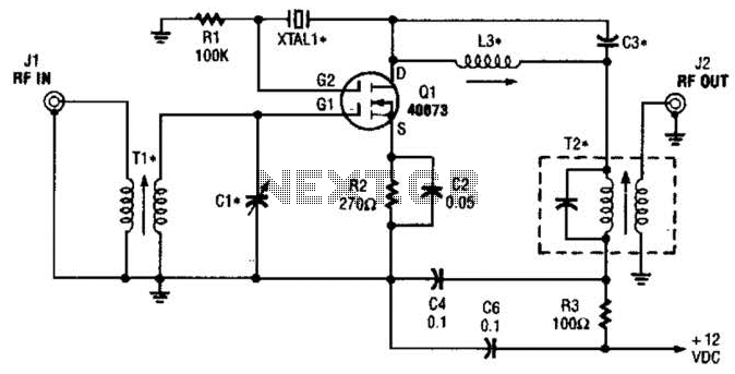
The described circuit leverages the unique characteristics of dual-gate MOSFETs, particularly their ability to handle multiple inputs and provide enhanced gain control. The integration of a crystal oscillator at the second gate (G2) facilitates precise frequency control, which is critical in applications such as radio frequency (RF) mixing.
In this configuration, L3 acts as an inductor that, together with C3, forms a resonant tank circuit with X1, which is the crystal oscillator. The choice of crystal type is vital, as third-overtone crystals can significantly extend the operational frequency range, allowing the circuit to function efficiently beyond 25 MHz.
T1 and C1 are essential for ensuring that the input frequency to the converter is accurately tuned. This tuning process is crucial for maximizing the mixer’s performance and minimizing signal distortion. The output from the mixer is then processed through T2, which is designed to efficiently transfer the intermediate frequency signal to the next stage of the circuit.
Overall, this design exemplifies a sophisticated approach to RF signal processing, merging traditional techniques with modern semiconductor technology to achieve high-frequency performance in compact circuitry. The careful selection of components and their configurations is vital for optimizing the circuit's functionality and reliability in practical applications. The second gate (G2) of a MOSFET can be used to incorporate a crystal oscillator into the same stage as a frequency mixer. Although old hat with tubes, this scheme is seldom seen in dual-gate MOSFET circuitry. L3, 03, and XI form the crystal oscillator, and T2 is an IF output transformer. T1 and 01 are tuned to the converter input frequency. This circuit should be useable up to 25 MHz or so, or higher with third- overtone crystals. 🔗 External reference
Related Circuits
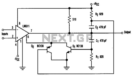
When the comparator's output transitions from low to high, the rising edge of the output pulse, differentiated by the Cl/Rl chain, activates Ql. This action blocks the comparator via its strobing input and maintains its output state for a...
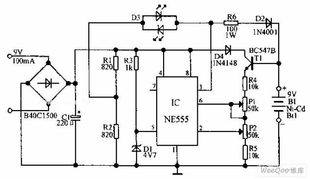
An automatic Ni-Cd battery charger circuit is depicted in the provided image. The internal comparator of the NE555 timer is configured to a reference voltage of 4.7V using a Zener diode. When the voltage at pin 6 exceeds this...
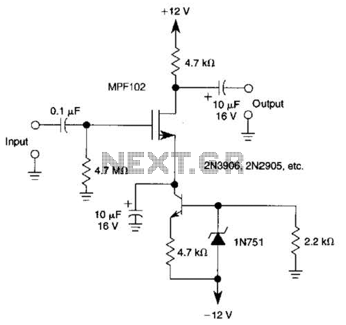
A current source (MPF102) in the source lead of the bipolar transistor 2N3906 allows for precise control of drain current. The circuit incorporates an MPF102 JFET configured as a current source, which is connected to the source terminal of a...
The first section of the 555 timer is configured as an astable oscillator, with R2 and C1 determining the frequency. The output is accessible at pin 5. The second section functions as a phase inverter, with its output available...
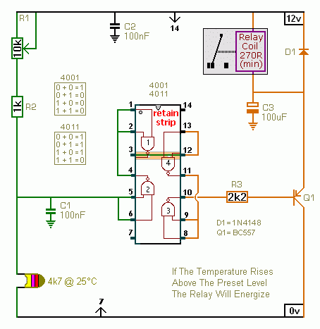
A CMOS 4001 or a CMOS 4011 can be utilized in this circuit, as both contain four two-input gates. The inputs of each gate are connected together, allowing them to function as simple inverters. This means that when both...
First circuit is for connecting VGA card to video projector or a monitor which accept VGA card frequencies and has RGB + Composite sync input. This circuit has been successfully used with Electrohome Projection Systems ECP 4100 data and...