How can small inductances be measured with a precision of at least two, and possibly three, significant digits? A review of the literature yielded limited results. One noteworthy circuit was detailed in the 2001 ARRL Handbook on page 26.22. A replica was constructed, successfully reproducing the results. Measurements with an accuracy of ±10% can be achieved with this clever device, covering a range from approximately 3 to 3000 µH, which is adequate for many amateur radio applications. A more precise and direct reading device was described by Robert Vreeland, W6YBT, in QEX (May 1989); however, it requires an expensive Fluke digital multimeter (DMM). This method reportedly provides accuracy in the range of 3-5%. The objective was to achieve 1% accuracy and measure smaller inductors down to about 0.5 µH, although this goal proved challenging. Various approaches were attempted, including several unsatisfactory bridges and the traditional grid-dipper method. By creating a parallel resonant circuit with a known-value capacitor and determining the resonant frequency with a grid-dip meter, the inductor's value can be estimated, but this typically yields only ±10% accuracy. A significant drawback of this method is the difficulty in coupling to toroidal inductors due to the concentration of the magnetic field in the core. To address this, a novel approach was devised: the inverse of the grid-dipper method. By connecting the unknown inductor in parallel with a known capacitance in an oscillator and measuring the oscillation frequency with a counter or accurately calibrated receiver, the inductance can be calculated from the known capacitance and oscillator frequency. This method has proven effective, yielding highly accurate measurements using readily available equipment and common components suitable for amateur radio operators. A simple, albeit rudimentary, breadboard was constructed on a small scrap of printed circuit board (PCB). The circuit diagram is presented in Figure 1, while Figures 2 and 3 display photographs of the breadboard and some inductors used for testing. In Figure 2, the "ugly" breadboard is shown alongside typical inductors, with the unknown inductor connected to alligator clips on the left and the counter or receiver connected via shielded cable to the clips on the right. The circuit functions as a Colpitts oscillator followed by an isolating source follower. Junction field-effect transistors (FETs) used are MPF-102s, and all capacitors influencing frequency are zero temperature coefficient (NPO) ceramics. Metal-film resistors are chosen for their stable RF characteristics, although exact values are not critical, allowing for ±5% tolerance resistors. Megohm resistors, with one end soldered to the PCB, serve as standoff insulators where necessary. A 9-V battery powers the circuit. Small alligator clips are soldered directly to the board for connections to the unknown inductor and to the frequency counter or receiver. Half-inch square pads were etched into the copper using a small drill for the ungrounded alligator clip connections. Careful attention must be paid to minimizing series inductance in the tuned-circuit path. The small clips are deemed suitable for the inductance range of interest. The circuit depicted in Figure 1 is effective for inductance values from 0.5 µH to over 1 mH. The oscillator operates reliably across a frequency range from a few hundred kilohertz to over 25 MHz. Although the signal level diminishes at the high-frequency (low-inductance) end, it remains sufficient to drive a counter or be audible in a receiver.How does one measure small inductances with a precision of at least two, and possibly three, significant digits A search of the literature produced scanty results. One interesting circuit was described in The 2001 ARRL Handbook on p 26. 22. I built a replica, and duplicated the results. Measurements with accuracy of ±10% can be made with that clever device from about 3 to 3000 µH, and that is good enough for many ham applications. A more accurate and direct reading device was described by Robert Vreeland, W6YBT, in QEX (May 1989); but an expensive Fluke DMM is required. Evidently, accuracy in the 3-5% range can be expected with W6YBT`s elegant method. Nonetheless, 1% accuracy and measurement of smaller inductors (down to about 0. 5 µH) was the goal, even if elusive. I attempted numerous approaches, including various unsatisfactory bridges and the old standby grid-dipper method.
By forming a parallel resonant circuit with a known-value capacitor and finding the resonant frequency with a grid-dip meter, the value of the inductor can be estimated. At best, this yields ±10% accuracy. A serious shortcoming of this method is that coupling to toroidal inductors is nearly impossible since the magnetic field is concentrated in the core.
(Did I miss something Has someone found a way to do this without influencing the unknown tuned circuit`s resonant frequency ) Finally, a simple solution occurred to me: the converse of the grid-dipper method. If we put the unknown inductor in parallel with a known capacitance in an oscillator and measure the frequency of oscillation with a counter or accurately calibrated receiver, we can calculate the inductance from the known tuned circuit capacitance and oscillator frequency.
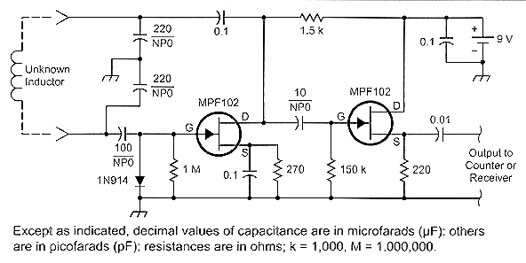
This method works very well, and I am convinced that it yields measurements of very good accuracy using equipment and common parts available to the average ham. A simple - and admittedly ugly - breadboard was built on a small scrap of PC board. Fig 1 shows the circuit diagram, and Figs 2 and 3 are photographs of the breadboard and some of the inductors used to test it.
Fig 2: The "ugly" breadboard and typical inductors. The unknown inductor is connected to the alligator clips on the left. The counter or receiver is connected to the clips on the right via a shielded cable. The circuit is a Colpitts oscillator followed by an isolating source follower. The junction FETs are MPF-102s, and all frequency-influencing capacitors are zero temperature coefficient (NPO) ceramics. Metal-film resistors are used for their stable RF characteristics, but exact values are not critical, so ±5% resistors will do nicely.
Megohm resistors with one end soldered to the PC board are used as standoff insulators where needed. A 9-V battery provides power. Small alligator clips are soldered directly to the board for connection to the unknown inductor and for connection to the frequency counter or receiver. Half-inch square pads were etched into the copper with a small drill for the ungrounded alligator clip connections.
Among other considerations, pay careful attention to minimizing series inductance in the tuned-circuit path. The small clips appear to be suitable for the inductance range of interest. The circuit in Fig 1 is satisfactory over the range of 0. 5 µH or less to over 1 mH. The oscillator operates reliably over the range from a few hundred kilohertz to over 25 MHz. The signal level does fall off at the high-frequency (low-inductance) end, but there is sufficient output to drive a counter or to be heard in a receiver.
A challenging issue in the design of traditional stereo tone controls is achieving synchronized movement of the potentiometers. Even minor discrepancies in synchronization can lead to phase and amplitude variations between the two audio channels. Additionally, linear potentiometers are...
A small transmitter board interfaces with a microcontroller and conductivity probe to measure liquid conductance and conductivity. Precise equations and measurements are provided for this microcontroller-controlled conductivity meter.
The described circuit consists of a compact transmitter board that serves as...
Savings on electricity bills can be achieved by utilizing alternative power sources. The photovoltaic module, or solar panel, described here can provide a power output of 5 watts. Under full sunlight conditions, the solar panel generates an output voltage...
This is an advanced version of a basic charge rate limiter that allows for the simultaneous charging of two battery packs from a single wall charger. For detailed circuit descriptions and parts lists, refer to the simple charger page....
Features: 3-12 V, 1 A, over-current protection. This is a simple yet reliable device based on one of the oldest integrated voltage regulators, the LM723. R2 sets the output voltage. The maximum current is determined by the value of...
4QD manufactures motor speed controllers, and all their H bridges utilize PWM. This is a simple switch circuit designed for reversing and stopping a motor without speed control. Two inputs, A and B, control the bridge. When both inputs...
We use cookies to enhance your experience, analyze traffic, and serve personalized ads.
By clicking "Accept", you agree to our use of cookies.
Learn more