
Acoustic Sensor

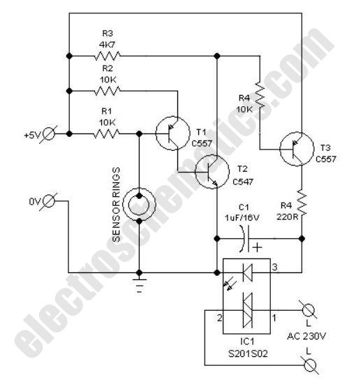
The described circuit functions as a microphone signal processing unit, where the sensitivity adjustment via potentiometer P1 allows the user to tailor the circuit's response to varying ambient noise conditions. The rectification of the audio signal by diodes D1 and D2 ensures that only positive voltage levels are processed, which is essential for the subsequent smoothing action of capacitor C4. This smoothing capacitor filters out high-frequency noise, stabilizing the voltage level that triggers the activation of transistor T2.
When the voltage across C4 exceeds the threshold of 0.5 V, T2 turns on, illuminating the connected LED, which serves as a visual indicator of the circuit's active state. The inverting behavior of transistor T3 ensures that the output signal reflects the presence or absence of sound detected by the microphone. In a state of silence, T3 is in a conducting state, maintaining the output at ground potential. Upon detection of an audio signal, T3 switches off, allowing the output to rise to +24 V, facilitated by resistors R4 and R5, which are appropriately sized to handle the required output current.
The design incorporates a safety feature with diode D4, which prevents damage from reverse polarity connections, a common issue in circuit assembly. Additionally, diode D3 serves to protect the output stage from potential over-voltage conditions that could arise from incorrect power supply connections. The choice of using two 4.7 kΩ resistors in parallel to achieve the necessary collector resistance for T3 ensures that the circuit can handle the required power dissipation safely while maintaining the desired performance characteristics. Overall, this circuit design demonstrates effective signal processing and protection mechanisms suitable for various audio applications.The sensitivity of the circuit can be adjusted using potentiometer P1 so that it does not respond to ambient noise levels. Diodes D1 and D2 recitfy the signal and C4 provides smoothing. As soon as the voltage across C4 rises above 0. 5 V, T2 turns on and the LED connected to the collector of the transistor lights. T3 inverts this signal. If the mic rophone receives no sound, T3 turns on and the output will be at ground. If a signal is detected, T3 turns off and the output is pulled to +24 V by R4 and R5. In order to allow for an output current of 10 mA, T3`s collector resistor needs to be 2. 4 k. If 0. 25 W resistors are to be used, then to be on the safe side this should be made up of two 4. 7 k resistors wired in parallel. Diode D4 protects the circuit from reverse polarity connection, and D3 protects the output from damage if it is inadvertently connected to the supply. Be the first of your friends to get free diy electronics projects, circuits diagrams, hacks, mods, gadgets & gizmo automatically each time we publish.
Your email address & privacy are safe with us ! 🔗 External reference
Related Circuits
In a class project, each student was required to select one of three technology platforms to design, simulate, prototype, and build, including PCB layout and ordering, all within a ten-week timeframe. The available platforms were: H-bridge Motor Controller, Infrared...
This compact water sensor alarm circuit emits a loud warning sound when a humidity sensor detects the presence of water. The circuit utilizes the low-power comparator LM1801 from National Semiconductor. A fixed reference voltage for the integrated circuit is...
The report provides information related to light sensors, photoresistors, comparators, and associated circuits. It contains extensive details regarding detection. Light sensors are devices that detect and respond to light levels in the environment. A common type of light sensor is...

The PCD3360 is a CMOS integrated circuit designed to replace the electro-mechanical bell in telephone sets. It meets most postal requirements, featuring selectable output tone sequences and input ringer frequencies. The circuit provides output signals suitable for driving a...
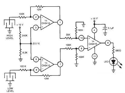
This liquid level sensor electronic circuit diagram utilizes a common CA3410 operational amplifier integrated circuit (IC). The sensor employs two plate sensors (or probes), one designated for detecting high liquid levels and the other for low liquid levels. If...
Install the PIR module hanging from a 3-meter high mast to cover a 10-meter radius area. Connect its supply and relay terminals to the finished and enclosed circuit, ensuring the correct polarity is observed. A 4-core screened cable can...
Warning: include(partials/cookie-banner.php): Failed to open stream: Permission denied in /var/www/html/nextgr/view-circuit.php on line 713
Warning: include(): Failed opening 'partials/cookie-banner.php' for inclusion (include_path='.:/usr/share/php') in /var/www/html/nextgr/view-circuit.php on line 713