
Dual level liquid sensor circuit design using CA3410 op amp
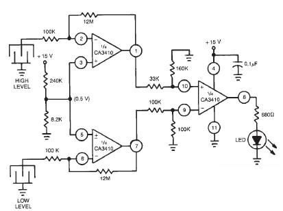
The liquid level sensor circuit operates by utilizing the CA3410 operational amplifier to compare voltage levels from the two probes. When the liquid level rises above the high-level probe, the voltage at this probe increases, which is detected by the operational amplifier. Similarly, when the liquid level falls below the low-level probe, the voltage drops. The operational amplifier is configured in a comparator setup, where it compares the voltages from both probes against a reference voltage set by a voltage divider circuit.
The output of the operational amplifier is connected to an LED, which serves as an indicator. When the liquid level is outside the defined range—either too high or too low—the operational amplifier's output switches state, causing the LED to light up. This visual indicator provides immediate feedback on the liquid level status.
To construct this circuit, the following components are typically required: the CA3410 operational amplifier, two conductive plates or probes for liquid level detection, resistors for the voltage divider and feedback network, and the LED for visual indication. Additionally, a suitable 15-volt DC power supply is essential to power the operational amplifier and ensure correct functionality of the circuit.
The design can be further enhanced by incorporating hysteresis into the operational amplifier configuration. This would prevent the LED from flickering when the liquid level fluctuates around the threshold levels. By adjusting the feedback resistors, the sensitivity of the sensor can be fine-tuned to accommodate different liquid types and environmental conditions, making this circuit versatile for various applications in liquid level monitoring.This level liquid sensor electronic circuit diagram is based on a common Ca3410 operational amplifier IC. This level liquid sensor electronic circuit use two plates sensors ( two probes ), one for the high level an one for low level.
If the level of the liquid is not in the adjusted range the LED will glow. The circuit require just a CA3410 op erational amplifier and other few common components. This dual liquid level sensor require a 15 volt DC power supply circuit. 🔗 External reference
Related Circuits
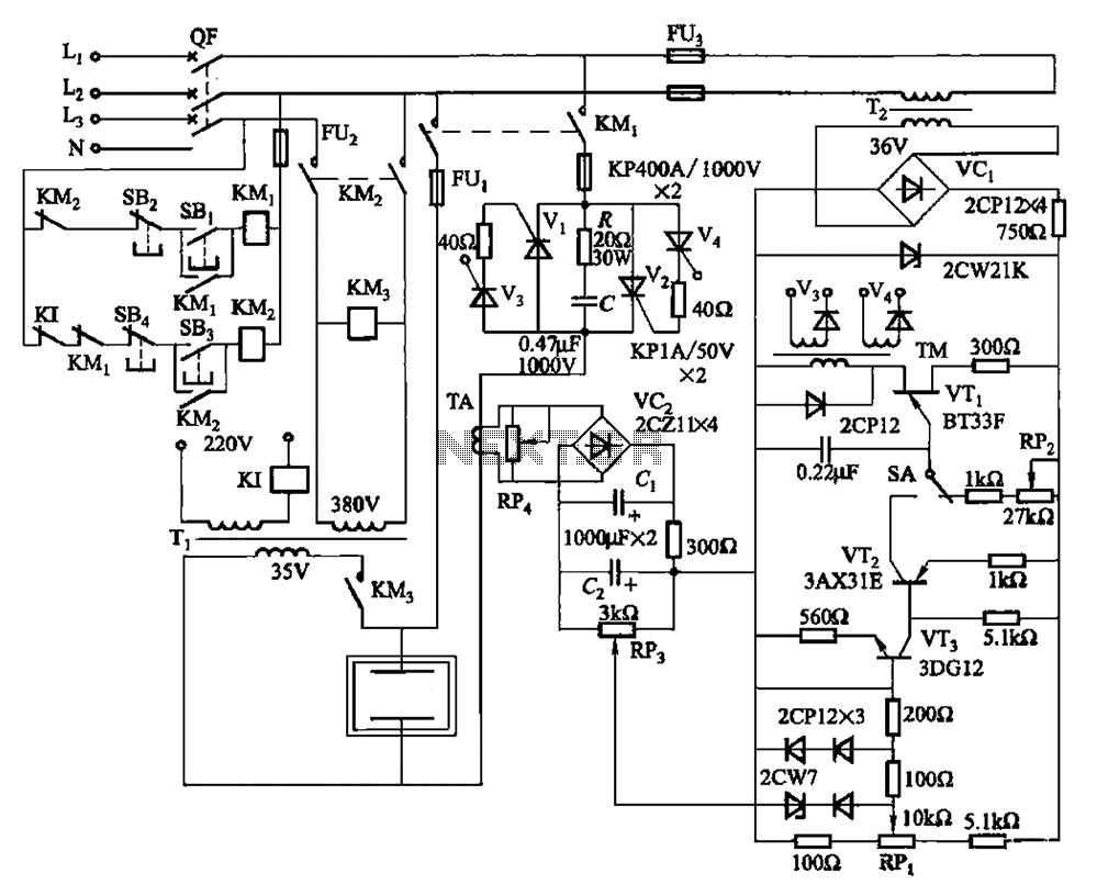
80 kW resistance salt bath furnace control circuit. The salt bath resistance furnace is a high-power device that employs fast start and temperature control technology to significantly save energy. The circuit includes a single-junction transistor (VTi) used as a...
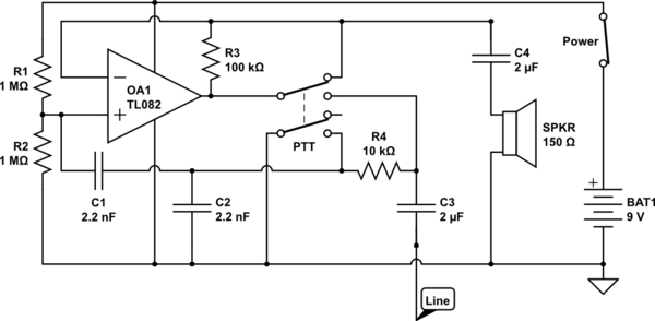
The circuit operates in receive mode, with the Push-To-Talk (PTT) switch enabling transmit mode. The speaker functions as both a microphone and a speaker. Most systems observed utilize a rocking armature transducer for the speaker. There is no base...
A Universal Power supply based on the L200 regulator, which includes an outboard pass transistor to boost output currents up to 4 amps. The described universal power supply utilizes the L200 voltage regulator, renowned for its versatility in providing adjustable...
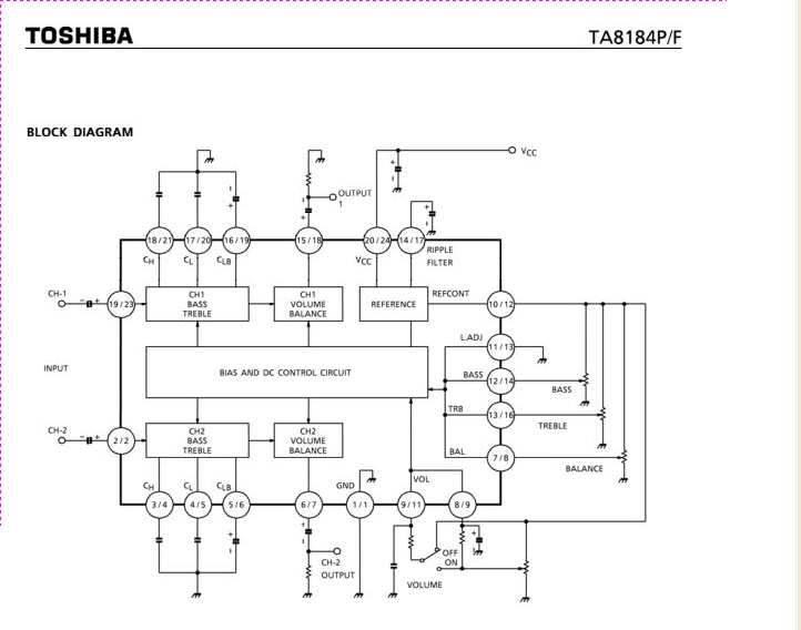
The TA8184P and TA8184F are DC-controlled integrated circuits designed for dual volume, balance, and tone (bass and treble) control. These ICs are suitable for applications in car stereos, radio cassette players, music centers, and TV multiplex sound receivers, providing...
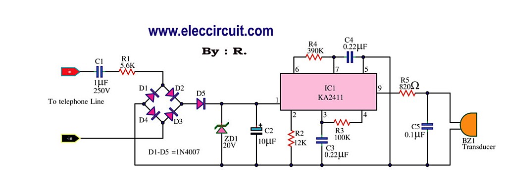
This circuit is designed to generate a loud ringing tone for an electricity bell in older telephones. It serves as a replacement for the original ringer, which may be lost, eliminating the need for a new phone. The circuit...
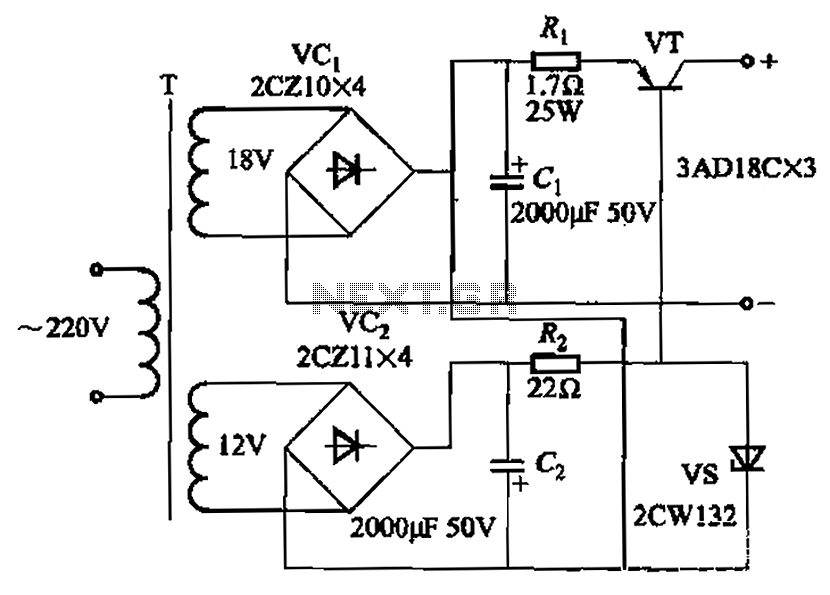
Characterized by a steady flow of power when the power supply voltage fluctuates or the load changes, this circuit maintains a constant load current. The output current of the circuit is illustrated in Figure 4A. When the load varies...