
Acoustic Sensor

The acoustic sensor circuit is designed to efficiently detect sound levels while ensuring operational safety. The electret microphone (MIC1) serves as the primary sensing element, converting sound waves into an electrical signal. The initial signal is weak and requires amplification; thus, transistor T1 is employed as a signal amplifier. The coupling capacitor C1 isolates the AC signal from the DC supply, allowing only the audio frequency components to pass through while blocking any DC offset.
Resistor R7 plays a critical role in defining the maximum collector current of T1, ensuring that it operates within safe limits. The feedback resistor R8 is essential for establishing the desired operating point of the amplifier, providing stability and linearity in the amplification process. The sensitivity of the system can be fine-tuned via potentiometer P1, which adjusts the gain of the amplifier to prevent false triggers from ambient noise.
Once the signal is amplified, diodes D1 and D2 are utilized for rectification, converting the AC signal into a pulsating DC signal. Capacitor C4 smooths this pulsating signal, creating a stable DC voltage that can be used for further processing. The threshold for activation is set at 0.5 V; when this threshold is exceeded, transistor T2 is activated, illuminating the LED to indicate sound detection visually.
Transistor T3 serves as an inverter in the circuit. In the absence of sound, T3 conducts, pulling the output to ground. Conversely, when a sound is detected, T3 turns off, allowing the output to rise to +24 V, facilitated by resistors R4 and R5. The design accommodates an output current of 10 mA, requiring careful selection of the collector resistor to ensure reliable operation. Using two 4.7 kΩ resistors in parallel for this purpose enhances reliability and heat dissipation.
Protection diodes D3 and D4 are critical for safeguarding the circuit against potential damage due to reverse polarity connections and inadvertent supply connections, respectively. This comprehensive design ensures that the acoustic sensor operates reliably in both industrial and domestic environments, providing a robust solution for sound detection applications.This acoustic sensor was originally developed for an industrial application (monitoring a siren), but will also find many domestic applications. Note that the sensor is designed with safety of operation as the top priority: this means that if it fails then in the worst-case scenario it will not itself generate a false indication that a sound is de
tected. Also, the sensor connections are protected against polarity reversal and short-circuits. The supply voltage of 24 V is suitable for industrial use, and the output of the sensor swings over the supply voltage range. The circuit consists of an electret microphone, an amplifier, attenuator, rectifier and a switching stage.
MIC1 is supplied with a current of 1 mA by R9. T1 amplifies the signal, decoupled from the supply by C1, to about 1 Vpp. R7 sets the collector current of T1 to a maximum of 0. 5 mA. The operating point is set by feedback resistor R8. The sensitivity of the circuit can be adjusted using potentiometer P1 so that it does not respond to ambient noise levels. Diodes D1 and D2 recitfy the signal and C4 provides smoothing. As soon as the voltage across C4 rises above 0. 5 V, T2 turns on and the LED connected to the collector of the transistor lights. T3 inverts this signal. If the microphone receives no sound, T3 turns on and the output will be at ground. If a signal is detected, T3 turns off and the output is pulled to +24 V by R4 and R5. In order to allow for an output current of 10 mA, T3`s collector resistor needs to be 2. 4 k. If 0. 25 W resistors are to be used, then to be on the safe side this should be made up of two 4. 7 k resistors wired in parallel. Diode D4 protects the circuit from reverse polarity connection, and D3 protects the output from damage if it is inadvertently connected to the supply.
🔗 External reference
Related Circuits

The PCD3360 is a CMOS integrated circuit designed to replace the electro-mechanical bell in telephone sets. It meets most postal requirements, featuring selectable output tone sequences and input ringer frequencies. The circuit provides output signals suitable for driving a...
This is a straightforward liquid detector that utilizes a relay to activate an evacuation valve. It can be employed for water or any conductive liquid. The liquid detector circuit operates by leveraging the conductivity of liquids to trigger a relay....
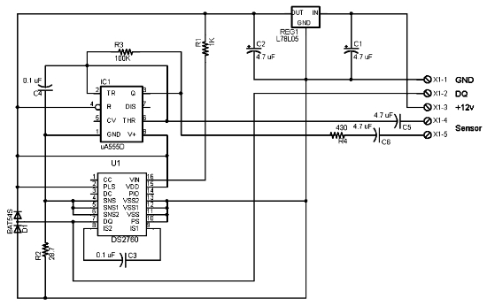
The following circuit illustrates the electrical circuit diagram for the 1976 Dodge Aspen. Features include the current register value of the IC DS2760. The electrical circuit diagram for the 1976 Dodge Aspen is a critical component for understanding the vehicle's...
This design circuit is for a mass air flow (MAF) sensor. The MAF sensor converts the volume of air entering the engine into a voltage signal. The main components of the MAF sensor include a thermistor, a platinum hot...
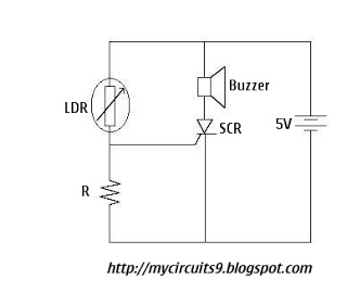
The Light Dependent Resistor (LDR) is a variable resistor whose resistance decreases as light intensity increases. Under normal light conditions, the resistance of the LDR is sufficiently high, resulting in an inadequate voltage across resistor R to activate the...
By attaching a standoff to the center of a 2-inch, 8-ohm speaker, it can be transformed into a vibration sensor with a natural resonance below 100Hz, which is quite effective. The implementation involves hanging the speaker from the lid...