
Liquid detector water sensor circuit
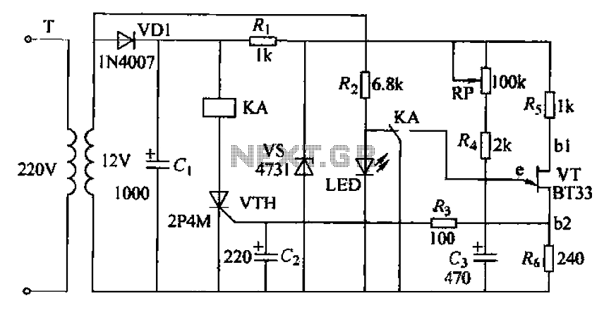
The liquid detector circuit operates by leveraging the conductivity of liquids to trigger a relay. The primary components of the circuit include a pair of conductive probes, a relay, a resistor, and a power supply.
When the probes come into contact with a conductive liquid, such as water, the liquid completes the circuit, allowing current to flow through the probes. This current is typically routed through a resistor to limit the amount of current that reaches the relay, protecting it from potential damage.
Once sufficient current flows through the probes, the relay is activated, which can then control a larger load, such as an evacuation valve. The relay acts as a switch that can open or close the valve based on the presence of liquid.
To enhance the reliability of the circuit, it is advisable to include a diode in parallel with the relay coil. This diode serves as a flyback diode, which protects the circuit from voltage spikes generated when the relay is de-energized.
The power supply for the circuit can vary based on the relay specifications, but it is essential to ensure that it matches the relay's voltage rating. The entire setup should be housed in a waterproof enclosure to prevent any short circuits or damage from the liquid being detected.
Overall, this liquid detector is a simple yet effective solution for monitoring the presence of conductive liquids and can be adapted for various applications where liquid detection is essential.This is a very simple liquid detector that use a relay to open an evacuation van. You can use it for water or any liquid that conduct electricity. Use any. 🔗 External reference
Related Circuits
This project is suitable for individuals who enjoy experimenting with electronics. It presents a low risk of damaging the unit. This project involves creating a simple electronic circuit that allows users to engage in hands-on experimentation without significant risk. The...
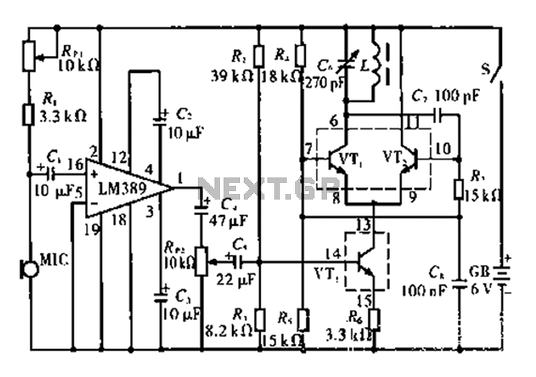
This circuit is tested and functional. The LM389 integrated circuit serves as the core element, where the voice channel number is acquired by the microphone (MIC) and converted into electrical signals. These signals are amplified by the volume control...

This is a simple 555 timer circuit suitable for oscillating applications. To slow down the strobe effect, replace the 220 µF capacitors with 1000 µF capacitors. For a faster strobe effect, use a 150 µF capacitor. Additionally, R1 can...
The circuit consists of a delay loop, discriminators, output circuits, power supply, and indicator lights, divided into five parts. The power regulation is achieved through a resistor (R), while the power regulator is constructed using a voltage source. In...
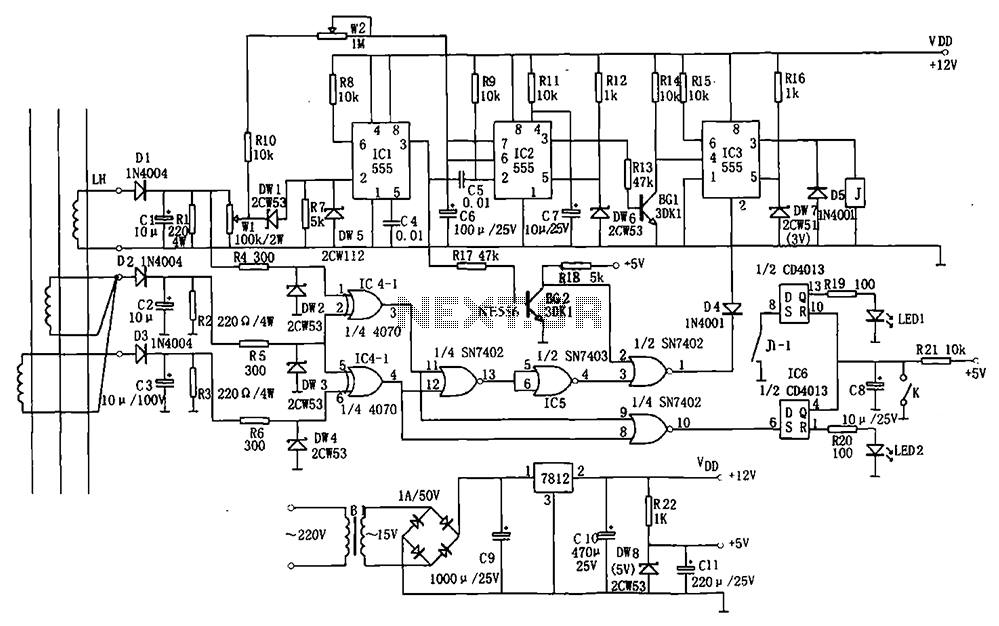
The electrical equipment overload and phase failure protection circuitry includes a +12V and +5V DC power supply, an AC transformer, voltage comparators, timers for blockade, a relay control circuit, and a phase loss protection circuit. The DC power supply...

Amplify a MG811 CO2 sensor to a range readable by an ATMEGA2560 (0-5V). Other analog sensors are in use, so it is preferred not to change the reference voltage on the ATmega. A module that scales the signal has...
Warning: include(partials/cookie-banner.php): Failed to open stream: Permission denied in /var/www/html/nextgr/view-circuit.php on line 713
Warning: include(): Failed opening 'partials/cookie-banner.php' for inclusion (include_path='.:/usr/share/php') in /var/www/html/nextgr/view-circuit.php on line 713