
Circuit Diagram Of Soil Moisture Sensor

The electrical circuit diagram for the 1976 Dodge Aspen is a critical component for understanding the vehicle's electronic systems. This schematic provides insights into the various electrical connections and components utilized in the vehicle, including the IC DS2760, which is integral for managing current flow and monitoring battery performance.
The IC DS2760 is a specialized integrated circuit designed for battery management systems. It features a current register that measures the charge and discharge currents of a battery, ensuring optimal performance and longevity. The circuit typically includes power management features, voltage references, and analog-to-digital conversion capabilities, allowing for precise monitoring of battery parameters.
In the context of the 1976 Dodge Aspen, the circuit diagram would include various components such as resistors, capacitors, and connectors that work in conjunction with the DS2760. Each component is labeled, and the interconnections are clearly defined to facilitate troubleshooting and maintenance. The power supply circuit would typically be connected to the vehicle's ignition system, ensuring that the DS2760 operates only when the vehicle is powered on.
Moreover, the circuit may also incorporate safety features such as fuses and diodes to protect against overcurrent and reverse polarity, which are critical for the reliability of the vehicle's electrical system. Understanding this circuit is essential for technicians and engineers who service vintage vehicles, as it helps ensure that all electrical components function harmoniously, maintaining the overall performance of the 1976 Dodge Aspen.The following circuit shows about Electrical CIrcuit Diagram For 1976 Dodge Aspen . Features: The value of the current register of IC DS2760 .. 🔗 External reference
Related Circuits

This series-feedback configuration of components provides a high input impedance and stable, wide-band gain video amplifier suitable for general-purpose applications. Below is the schematic representation of the circuit. The described video amplifier circuit employs a series-feedback topology, which is instrumental...
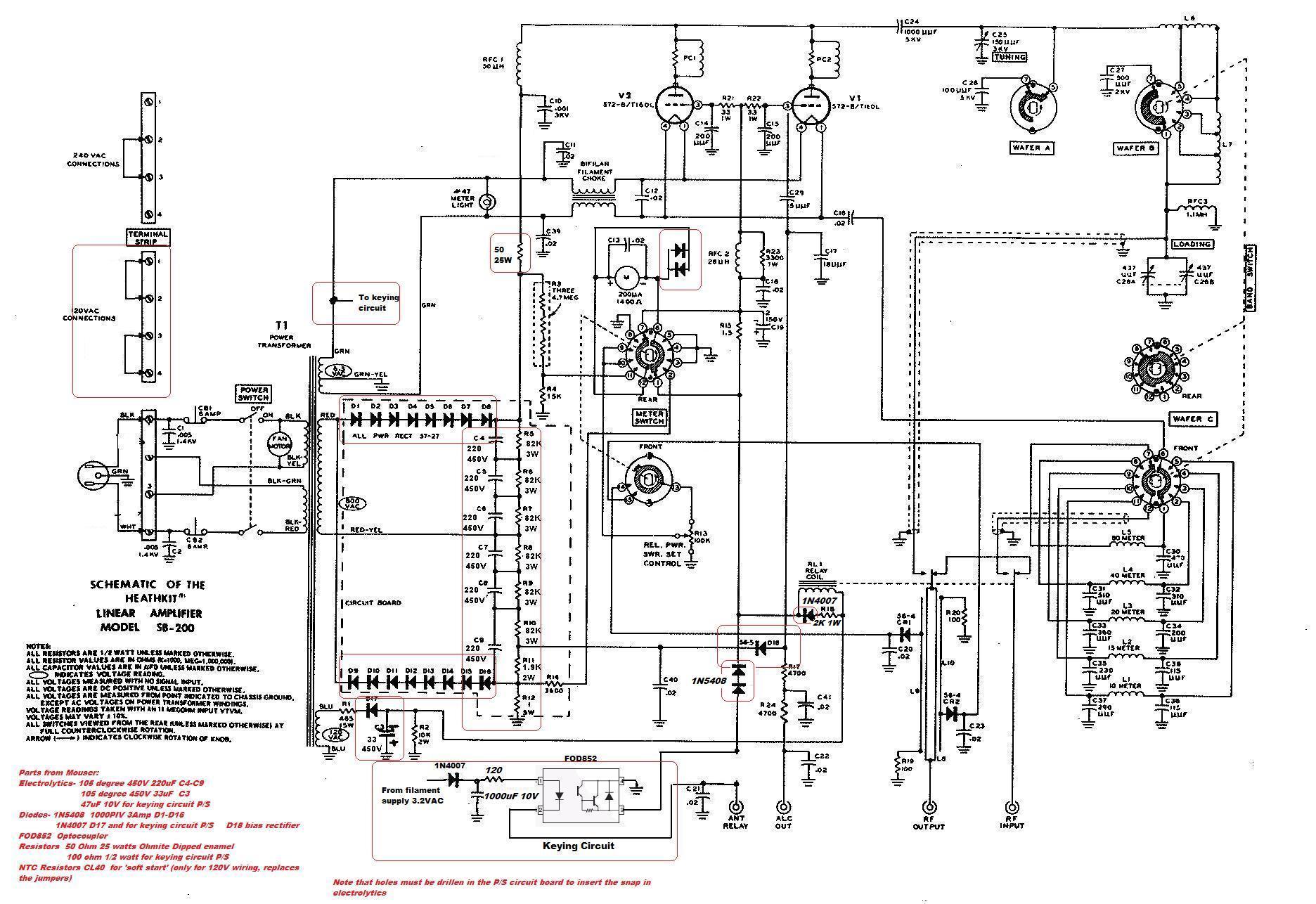
This circuit serves as a cost-effective alternative to commercially available keying circuits. It has been successfully implemented in the SB-200 amplifier. A schematic of the modified SB-200 is provided. The described circuit is designed to function as a keying mechanism...
Volvo S40 Wiring Diagram Radio 1997 Manual PDF Download. The Volvo S40 wiring diagram for the radio from the 1997 model year provides a detailed schematic representation of the electrical connections and components involved in the vehicle's audio system. This...

A gas leak detector circuit that detects the leakage of LPG gas and alerts the user through audio-visual indications. The circuit operates off a 9V PP3 battery. A Zener diode is used to convert 9V into 5V DC to...
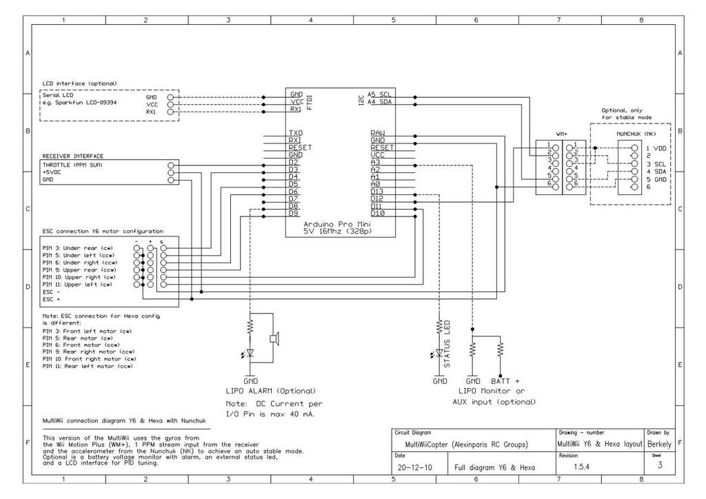
This is a video showcasing a test flight of the Quad Rotor Observer (QRO) v8, which is equipped with the FCWii board, Wii Motion Plus gyroscopes, and Nunchuk accelerometers. The Quad Rotor Observer (QRO) v8 is an advanced quadcopter designed...

A semiconductor color sensor is designed to identify the color of an object using three photodiodes (PD1, PD2, PD3) and three corresponding color filters (X-PHOTO, Y-PHOTO, Z-PHOTO). Each photodiode is paired with a specific color filter: red (R), green...