
Active Antenna for Medium Wave

The circuit employs a telescopic whip antenna as the primary input, which is particularly effective for medium wave reception. The preamplifier's design allows it to amplify weak radio signals, making it suitable for applications where signal strength is a concern. The use of a dual-gate MOSFET (TR1) is crucial, as it enables better handling of varying signal levels and provides enhanced gain control through the application of voltage at gate 2.
The tuning process is facilitated by the combination of inductors (L1 and L2) and varicap diodes, which adjust the resonant frequency of the circuit to match the desired frequency range. This configuration not only allows for fine-tuning but also ensures that the circuit remains selective, minimizing interference from adjacent frequencies.
The stabilization of the power supply through the use of ZD1 (a zener diode) and resistor R6 is essential for maintaining consistent performance across different operating conditions. This stability is particularly important in RF applications, where fluctuations in supply voltage can lead to variations in gain and overall circuit performance.
The output stage, consisting of TR2 and TR3, is designed to deliver a low output impedance, making it compatible with standard 50 Ω receivers. This is achieved by using TR2 in a common emitter configuration for voltage amplification and TR3 as an emitter follower to buffer the output. This arrangement ensures that the circuit can drive the input of the receiver effectively, providing a strong and clean signal.
For versatility, the circuit can be adapted for use on different frequency bands by simply changing the values of the inductors L1 and L2. The inclusion of switches or relays for this purpose adds an extra layer of functionality, allowing the user to switch between bands seamlessly. This feature makes the active antenna suitable for a variety of applications, from amateur radio to professional broadcasting, where flexibility and performance are paramount.This circuit is designed to amplify the input from a telescopic whip antenna. The preamplifier is designed to cover the medium waveband from about 550Khz to 1650Khz. The tuning voltage required is 1 to 12 volts and can be obtained from a 10k potentiometer connected to the 12 Volt power supply. RV1 is the gain control allowing weak signals to be am plified or strong signals to be attenuated. The control voltage is applied to gate 2 of TR1, a dual-gate MOSFET, the signal voltage applied via gate 1; the input signal being tuned via L1 and the two varicap diodes at the MOSFET`s input and also by L2 and the varicaps at the MOSFET`s drain terminal. Both tuned circuits provide high selectivity across the entire tuning range. To aid stability the MOSFET stage is fed from a stabilized supply consisting of ZD1 and R6. To drive low impedance (50 ohm) receivers, the medium output imepedance of the BF981 stage is enhanced by the composite amplifier made from TR2 and TR3.
TR2 is operating in common emitter boosting voltage levels by just over 2, TR3 is operating in emitter follower giving the circuit a low output impedance. Finally this active antenna can be used on other bands by changing the values of L1 and L2. To perform on multiple bands switches or relays can be used to change the value of L1 and L2. 🔗 External reference
Related Circuits
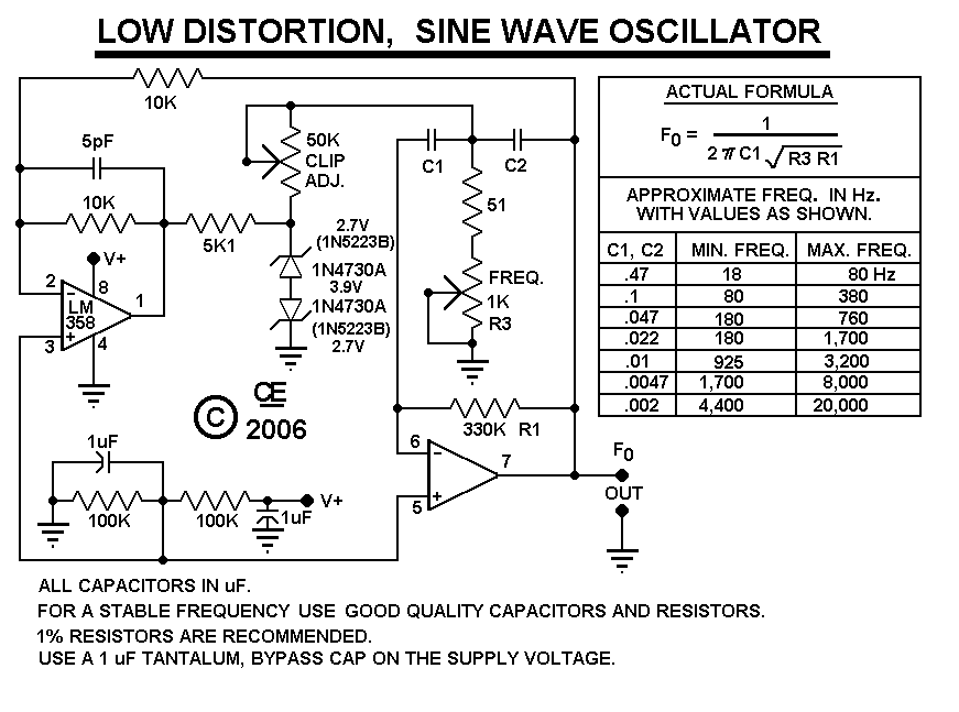
After constructing the device, adjust the frequency to the desired level using the "Frequency Control." Then, utilize an oscilloscope to fine-tune the waveform for optimal performance with the "Clip Control." The sharp rise and fall times of square waves...
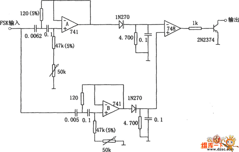
Replacing the LC modulation circuit with an active filter allows for the elimination of large and costly inductance coils in frequency shift key control demodulators. This approach not only reduces the size of the circuit but also enhances the...
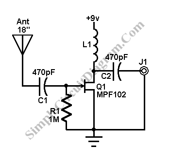
This AM/FM antenna booster circuit amplifies the broadband signal from the antenna. This antenna booster is designed to work for FM, AM, and SW receivers. The AM/FM antenna booster circuit is an essential component for enhancing radio reception across...

Building a signal generator is an essential project for any analog DIY enthusiast. While already possessing a bench signal generator, the intention was to create a compact, battery-powered device for quickly testing new effect designs. An enclosure from a...
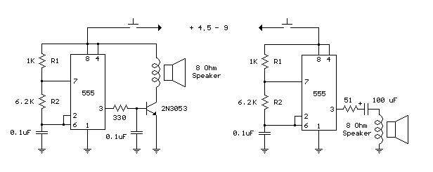
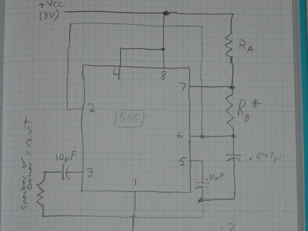
The following circuit is a basic 555 square wave oscillator. Features include a 1 kHz tone, simple circuitry, a current limit of 200 mA, reduced inductive voltage, and a supply voltage range of 4.5 to 9 volts. Components used...
A new project has been selected for the upcoming year, which is an improvement over the previous project, a homemade x-ray machine. The chosen project involves developing a safer and more efficient electronic device, replacing the homemade x-ray machine that...