
Low Cost, 16Hz - 100kHz Sine-wave Generator circuit

The circuit design emphasizes the importance of using readily available components, ensuring accessibility for enthusiasts in various regions. The choice of a Wein bridge oscillator is particularly beneficial due to its inherent stability and low distortion characteristics, making it suitable for audio applications. The integration of feedback mechanisms using optical components enhances the circuit's adaptability and performance, allowing for precise frequency control without the drawbacks associated with traditional dual-gang potentiometers. The thoughtful arrangement of components and the innovative use of feedback ensure that the circuit not only meets the desired specifications but also remains user-friendly for those engaged in DIY electronics projects. Overall, this signal generator design exemplifies the principles of analog electronics while providing a practical solution for testing and developing audio effects.Building your own signal generator is a rite of passage for any analog DIYer, but it`s one I took a long time to get around to. I already have a bench signal generator, but I decided it would be useful to have a small battery powered device that I could quickly test new effects designs with.
Plus I had an enclosure from a failed project that reall
y needed to be put to good use. Building a sine wave oscillator is easy. Building a low distortion sine wave oscllator is less easy, and building one that can also be varied over a wide range is harder still. I could have used a ready made function generator IC like the ICL8038 or XR2206, but that seemed like cheating.
Plus those parts may be difficult to find in some parts of the world, and have a clouded future, and I wanted to create something using generic parts that anyone could build. The final circuit performs remarkably well, with less than 0. 1% THD+N in the upper ranges. The logical choice for a wide range sine wave oscillator is a Wein bridge, as shown in the image on the right.
This works by applying positive feedback around a gain block using a simple RC-CR band-pass filter. The circuit will oscillate at its centre frequency where the filter`s gain (and therefore the loop gain) is highest. If the two resistors and two capacitors are the same then this occurs at a frequency of: The centre frequency -and therefore the frequency of oscilation- can be varied by altering R and/or C, and this is usually accomplished by using a dual-gang pot for the resistors in the Wein network.
This allows smooth control over the frequency for about one decade. Other decades are accessed by switching in different pairs of capacitors, each ten times larger/smaller than the last. However, ordinary dual gang pots are rather bulky, fairly expensive, and poorly matched, so I wanted to avoid them.
Ideally the gain of the amplifier needs to be the exact inverse of the gain of the Wein bridge network at the centre frequency. If this condition is met, the loop gain will be exactly 1; just enough to maintain oscillation with no distortion.
Some simple algebra shows that the Wein network has a centre gain of 1/3, so the amplifier needs a gain of 1/(1/3)= 3. This can be set by a negative feedback network just like any non-inverting opamp circuit. However, in practice we need some kind of automatic adjustment of the negative feedback to maintain this condition under all circumstances.
In my circuit this is controlled by an LED and LDR combo. These components need to be mounted facing one another and sealed from exturnal light- heatshrink tube is an old favourite for this. Looking at the schematic, 9V is supplied either by a battery or a mains adapter. D3 provides polarity protection. R10+R11 form a potential divider that produces a voltage mid-way between the rails, and this is buffered by U2B, effectively creating a bipolar supply from unipolar one, just like in most effects pedals.
U1b does the interesting bit by overcoming the need for a dual-gang pot. Because only one resistance in the Wein network is varied, the smaller this resistance becomes the low the gain of the Wein network becomes. The main amplifier U2a therefore needs more gain (less negative feedback) to compensate and maintain oscillation.
U2a works as a current-to-voltage converter, taking the current flowing in the variable arm of the Wein network and converting it into a voltage that is applied to R2, which is part of the negative feedback network. This stage is therefore bootstrapping R2, effectiely creating a current controlled resistor. As the frequency pot is reduced in value, more current flows in it, which is converetd to a larger signal by U1b which in turn makes more current flow in R2, making R2 seem smaller in value.
This reduces the negative feedback, which is exactly what we needed. The gain of U2a is itself controlled optically by U1a (see below). All this does
Related Circuits
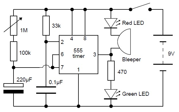
This adjustable analog timer circuit begins timing when it is activated. A green LED illuminates to indicate that the timing is in progress. Upon completion of the set time period, the green LED turns off, a red LED activates,...
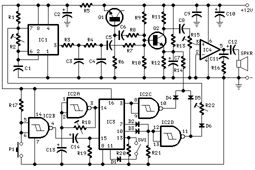
This circuit generates a two-tone effect similar to the sound of a cuckoo. It can be utilized for doorbells or other applications due to its integrated audio amplifier and loudspeaker. When used as a sound effect generator, it can...
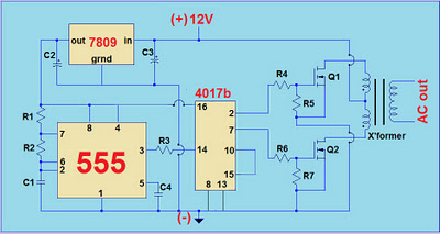
This project involves a simple 12V to 220V modified sine-wave inverter utilizing a 555 timer IC and a CD4017 decade counter. The inverter is capable of delivering 300W of continuous power and approximately 500W of maximum power output for...
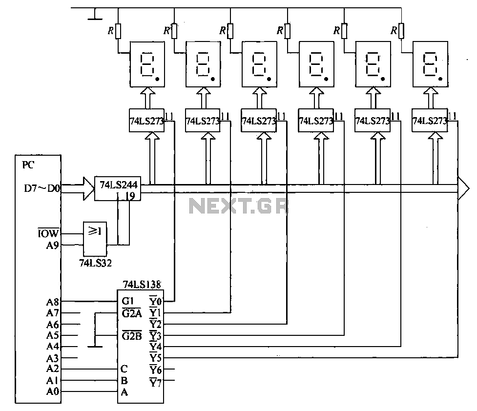
The static display circuit is illustrated in Figure 6. The 74LS244 acts as bus drivers, and six figures represent a public bus, each equipped with an LED display latch (like the 74LS273) connected to the code for latching the...
The count switching circuit consists of an electronic switch and a pulse delay circuit for control. The count switching circuit is designed to manage the switching of signals in a controlled manner. The electronic switch serves as the primary component...
This schematic illustrates a highly sensitive microphone preamplifier circuit designed to amplify the gain of a microphone or enhance audio signals originating from a microphone. The circuit is straightforward, comprising only a few components, and can be assembled in...