
Active Antenna HF/VHF/UHF 3-3000MHz
In its basic form, an active antenna utilizes a small whip antenna that feeds incoming RF to a pre-amplifier, with the output connected to the antenna input of a receiver. Active antennas are generally designed for receive-only operation and should not be used with transceivers, as transmitting can damage their components. A well-designed broadband active antenna takes into account the field strength of the desired signal (measured in microvolts per meter of antenna length), atmospheric and other noise, the antenna's diameter, radiation resistance, and reactance at various frequencies, in addition to the efficiency and noise figure of the amplifier circuit.
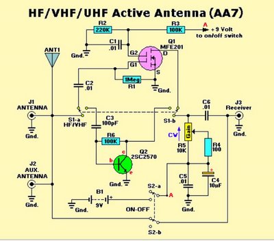
The schematic diagram of the AA-7 includes two active elements: Q1 (an MFE201 N-Channel dual-gate MOSFET) and Q2 (a 2SC2570 NPN VHF silicon transistor). These transistors form the basis of two independent, switchable RF pre-amplifiers. Two double-pole double-throw (DPDT) switches are integral to the operation of the AA-7. Switch S1 selects one of the two pre-amplifier circuits (either HF or VHF/UHF), while switch S2 turns off the power to the circuit and couples the incoming RF directly to the receiver’s input. This configuration provides the receiver with non-amplified access to the auxiliary antenna jack (J1) and the on-board telescoping whip antenna.
When switch S2 is in the power-on position, the input and output jacks are disconnected, and a 9-volt battery (B1) powers the circuit. In the schematic’s indicated position for switch S1, incoming RF is directed to the HF pre-amplifier circuit centered around Q1. This HF pre-amplifier operates at an exceptionally low noise level, making it suitable for receiving weak continuous wave (CW) and single-sideband signals. Conversely, when S1 is switched to the other position, the captured signal is routed to the VHF/UHF pre-amplifier based on Q2, which demonstrates excellent characteristics across VHF to microwave frequencies. The adjustable on-board whip antenna can be tuned to resonance across a significant portion of the VHF-UHF spectrum (antenna length in feet = 234 divided by the frequency in MHz), rendering the VHF/UHF mode ideal for indoor and portable use with VHF scanners and other receivers.
Both modes are applicable for tuning 3-30 MHz HF signals. While the VHF/UHF pre-amplifier provides greater gain than the HF pre-amplifier, it also has a higher noise level. Users can select either amplifier to capture the desired signals by testing both positions. The RF gain control (R5) is available to adjust the output of either amplifier. It is important to note that the AA-7 is not intended for transmission purposes (including Ham, Maritime, or CB). If used with any transceiver, precautions should be taken to prevent accidental transmission.This Blog show the Different Electronics Circuit Design, Application, Fields and Resources which could help students, engineers, professionals, and common people whose interest is in electronics! For your comments, suggestions, or your looking for a circuit or design, or a electronics designer, please send you Inquiries to pcb1001@gmail.
com. We are happy to help and attend to your concerns. If you have a shortwave or high-frequency receiver or scanner that is struggling to capture signals with a short, whip antenna, and you`d like the kind of performance that a 60-foot `longwire` antenna can provide but lack the space to put one up, consider building the AA-7 HF/VHF/UHF Active Antenna described in this article. The AA-7 is a relatively simple antenna that is designed to amplify signals from 3 to 3000 MegaHertz, including three recognized ranges: 3-30Mhz high-frequency (HF) signals; 3-300Mhz very-high frequency (VHF) signals; 300-3000MHz ultra-high (UHF) frequency signals.
Those bands are typically occupied by shortwave, ham, government, and commercial radio signals. In its simplest form, an active antenna uses a small whip antenna that feeds incoming RF to a pre-amplifier, whose output is then connected to the antenna input of a receiver. Unless specifically designed otherwise, all active antennas are intended for receive-only operation, and thus should not be used with transceivers; transmitting into an active antenna will probably destroy its active components.
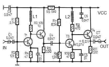
A well designed broadband active antenna consider field strength of the desired signal (measured in microvolts per meter of antenna length), atmospheric and other noise, diameter of the antenna, radiation resistance, and antenna reactance at various frequencies, plus the efficiency and noise figure of the amplifier circuit itself. Figure shows the schematic diagram of the AA-7, which contains only two active elements; Q1 (an MFE201 N-Channel dual-gate MOSFET) and Q2 (a 2SC2570 NPN VHF silicon transistor).
Those transistors provide the basis of two independent, switchable RF pre-amplifiers. Two double-pole double-throw (DPDT) switches play a major role in this operation of the AA-7. Switch S1 is used to select one of the two pre-amplifier circuits (either HF or VHF/UHF). Switch 2 is used to turn off the power to the circuit, while coupling the incoming RF directly to the input of the receiver. That gives the receiver non-amplified access to the auxiliary antenna jack, at J1, as well as the on-board telescoping whip antenna.
With switch S2 in its power-on position, the input and output jacks are disconnected and B1 (a 9 volt battery) is connected to the circuit. With switch S1 in the position shown in the schematic, incoming RF is directed to the HF pre-amp circuit built around Q1 (an MFE201 N-Channel dual-gate MOSFET).
The HF pre-amp operates with an exceptionally low noise level, and is ideal for copying weak CW and singe-side band signals. When S1 is switched to the other position, the captured signal is coupled to the VHF/UHF pre-amp built around Q2 (a 2SC2570 NPN VHF silicon transistor), which has excellent VHF through microwave characteristics.
With the on-board whip antenna adjustable to resonance through much of the VHF-UHF region (length in feet = 234 divide by the frequency in MHz), the VHF/UHF mode is ideal for indoor and portable use with VHF scanners and other receivers. Either mode can be used when tuning 3-30 MHz HF signals. The VHF/UHF pre-amp offers higher gain than the HF pre-amp, but also has a higher noise level. You can easily choose either amplifier for copying any signal; of interest-just try both positions. The RF gain control (R5) can be used to trim the output of either amplifier. Caution: The AA-7 is not intended for transmitting operation (be it Ham, Maritime, or CB); if it is used with a transceiver of any kind, make sure it is not possible to transmit by accidentally pressing
🔗 External reference
Related Circuits
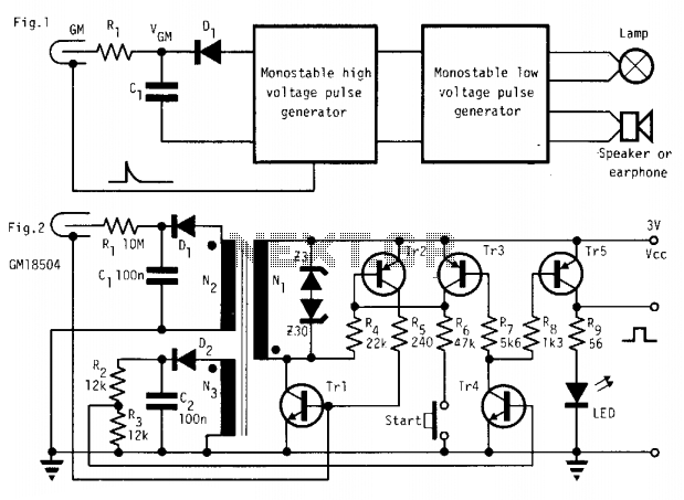
In the absence of radiation, no current is drawn. At normal background radiation levels, the power consumption is extremely low. The instrument may be left on for several months without changing batteries. In this way, the detector is always...
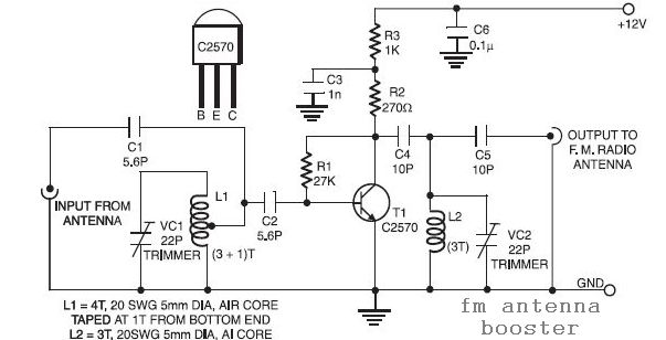
The input coil L1 is composed of four turns of 20 SWG enamelled copper wire, wound slightly spaced over a 5mm diameter former. It is tapped at the first turn from the ground lead side. Coil L2 is similar...
The elements diameter of the antenna may vary between 5...8mm and the dipole diameter may vary between 8...12mm (12mm recommended) without the need of changing anything to the length or spacing. All elements except the dipole are electrically connected...
A simple and effective antenna amplifier can be built using the provided circuit diagram. This amplifier is designed for the frequency range of 35 kHz to 150 MHz. It utilizes transistors, offering a low non-linearity of 3 dB and...
All ATL-3 loop windings are centre tapped and balanced w.r.t. their amplifier/receiver chassis ground, and therefore electric field interference pick up tends to self cancel. Magnetic noise fields, e.g. televisions and the electric meter box, or electromagnetically radiated interferences,...
This new loop antenna by Graham Maynard is his best design yet and I am proud to be the first to present his work. It uses one, six foot square, six turn loop, and is aperiodic in nature, covering...