
Active ferrite rod antenna for HF
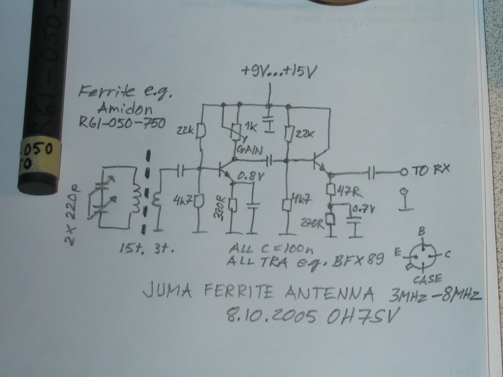
The circuit features a red connector intended for an optional external antenna, which enhances signal reception capabilities. This connector is linked to the secondary winding of the circuit, allowing for effective signal amplification. The black connector serves as the ground wire, establishing a common reference point for the circuit and ensuring proper operation.
To improve the circuit's stability, particularly under high-gain conditions, two bypass capacitors rated at 100nF are incorporated into the design. These capacitors are strategically soldered from various +9V supply points to the ground plane. Their purpose is to filter out noise and provide a stable voltage supply, which is crucial for maintaining performance in sensitive electronic applications.
The ferrite component utilized in this circuit is the Amidon R61-050-300. Ferrite beads are often employed to suppress high-frequency noise and improve signal integrity. This specific ferrite is selected based on its impedance characteristics at the operating frequencies of the circuit, contributing to the overall reliability and efficiency of the design.
The integration of these components forms a cohesive unit that enhances the functionality and performance of the electronic circuit, ensuring it meets the demands of various applications while maintaining stability and signal quality.The red connector is for an optional external antenna wire and the black connector is for a ground wire. The red is wired to secondary winding and the black is connected to the circuit ground plane. Additionally two by-pass capacitors (100n) are soldered from different +9V locations to the GND plane for stability in high gain setting.
The ferrite is Amidon R61-050-300. Click the pictures. 🔗 External reference
Related Circuits
In the pursuit of effective small antennas, an active whip antenna was constructed. This compact vertical antenna is linked to a preamplifier, which serves to convert the high impedance of the 50-ohm receiver and coaxial cable. Various designs exist...
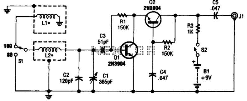
This antenna may assist in minimizing power-line noise. It consists of a plastic hula hoop or conduit with a diameter of 3 feet, which is covered with aluminum foil to serve as a shield for LI and L2. LI...
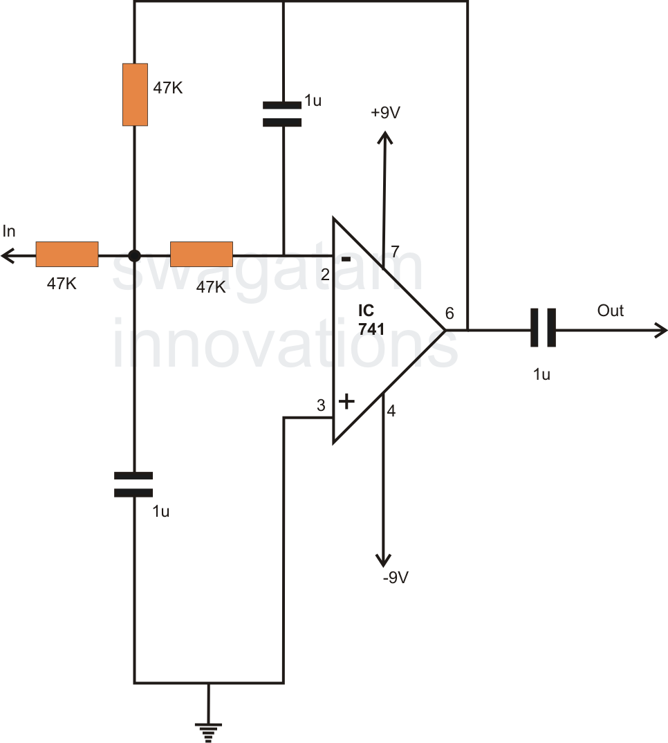
In electronics, filter circuits are primarily used to restrict the passage of certain frequency ranges while allowing other frequency bands to proceed to subsequent stages of the circuit. A high-pass filter circuit permits only frequencies that exceed a specified...
The reference design for an automotive antenna incorporates an AM/FM low-noise amplifier (LNA) intended for use in active antenna modules. The article outlines the capabilities, features, and design simplicity associated with the AM/FM active antenna LNA. The automotive antenna reference...
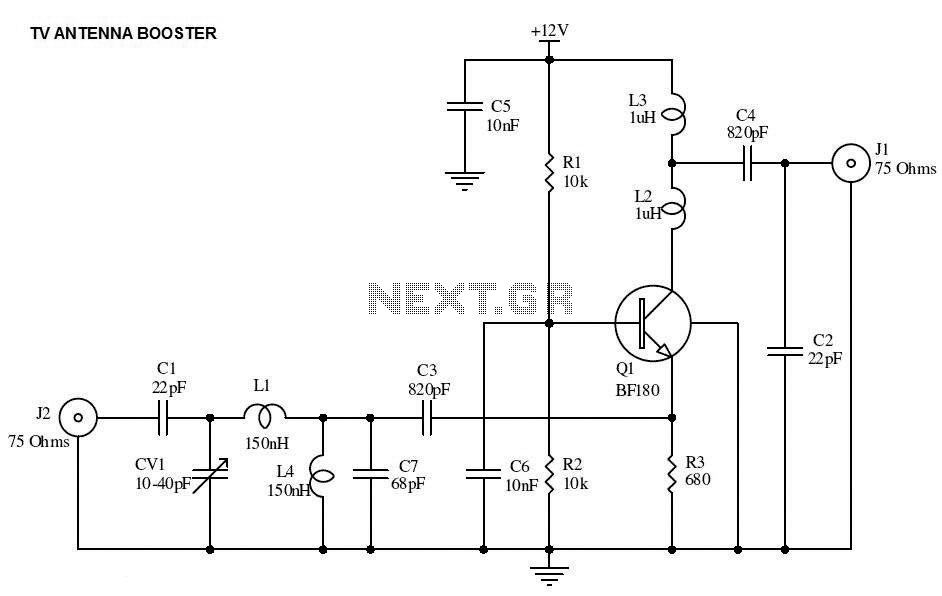
This is the circuit diagram of a UHF band TV antenna booster with a 15dB gain power. This low-cost antenna booster is simple and easy to build. This circuit is based on the BF180 UHF transistor. The first stage...
Below is a schematic of a tunable FM antenna booster or FM antenna amplifier circuit that can be utilized to amplify faint or distant FM signals. The circuit employs two transistors to enhance signal gain to an optimal level....