
fm antenna booster
The tunable FM antenna booster circuit is designed to improve the reception quality of FM radio signals, particularly in areas where signal strength is weak. The core components of the circuit are two 2N3904 transistors, which are configured in a way that allows them to amplify the incoming radio frequency (RF) signals effectively.
The first transistor functions as a common-emitter amplifier, where the input signal from the antenna is fed into the base terminal. This configuration provides a high input impedance and low output impedance, allowing for effective signal amplification. The amplified signal is then passed to the second transistor, which further boosts the gain.
The tunable aspect of the circuit is achieved through the use of variable capacitors or inductors, which can be adjusted to match the frequency of the desired FM station. This tuning capability allows the circuit to selectively amplify specific frequencies while minimizing interference from other signals.
Additional components such as resistors and capacitors are included in the circuit to stabilize the operation of the transistors and filter out unwanted noise. Proper biasing of the transistors is crucial to ensure they operate within their optimal range, which maximizes gain and minimizes distortion.
Power supply considerations are also essential for the performance of this circuit. A stable DC voltage source is required to power the transistors, typically in the range of 9V to 12V, depending on the design specifications.
Overall, this tunable FM antenna booster circuit is an effective solution for enhancing FM signal reception, making it suitable for use in various applications, including home audio systems and portable FM radios.Below is a schematic of a tunable FM antenna booster or FM antenna amplifier circuit which can be used to amplify the faint or distant FM signals. The circuit is using two transistors to increase signal gain to good level. The transistors are general purpose 2N3904. The circuit is using two tunable 🔗 External reference
Related Circuits
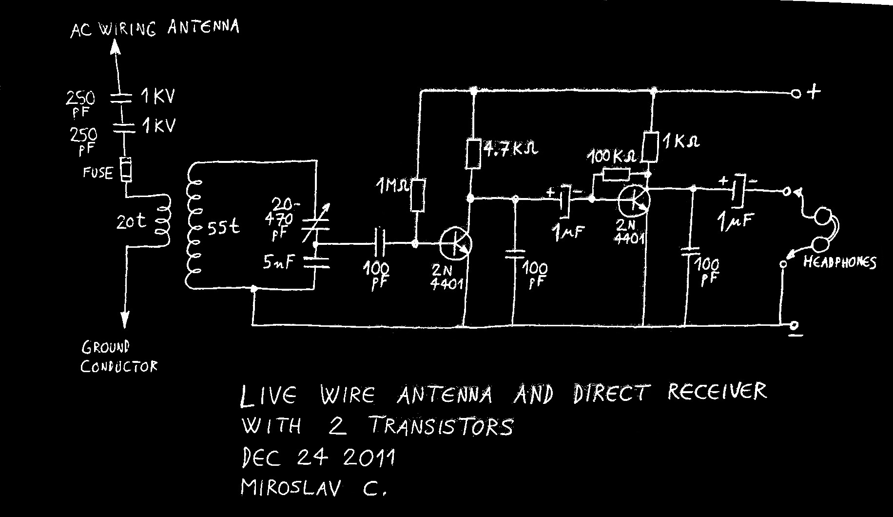
Using live or neutral wire in AC household wiring as a receiving antenna is feasible only with a high-voltage capacitor inserted between the receiver antenna terminal and the live or neutral wire. This AC wiring antenna solution is often...
This UHF wideband amplifier (Ultra High Frequency amplifier) provides a total gain of 10 to 15 dB in the frequency range of 400 to 850 MHz, making it suitable for areas with weak TV signals. For optimal performance, the...
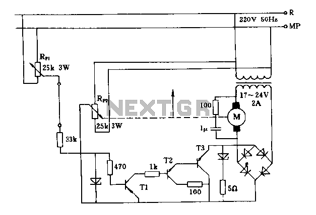
The FIG potentiometer RP2 has a sliding contact that is directly connected to the antenna. The system operates such that only when potentiometers RP1 and RP2 are positioned identically, do the non-conductive transistors and rectifier bridge remain off, resulting...
This antenna tuning unit (ATU) allows half-wavelength or longer wire antennas to be matched to the 50-ohm antenna input of 27-MHz Citizens Band (CB) radios. The ATU is particularly useful in situations where a wire antenna is less visually...
Here's something that has always bugged me: light waves are about 5000 Angstroms in wavelength, while atoms are more like 1 Angstrom across. Atoms are thousands of times smaller than light waves, yet atoms obviously interact very strongly with...
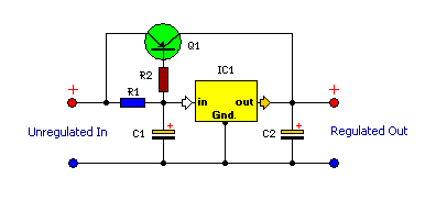
This is a compact and highly functional circuit that can be constructed on a veroboard. Voltage regulators such as the LM708 and LM317 series (among others) may occasionally require a load. The circuit utilizes voltage regulators, which are essential components...