
how to make simple active low pass
Filter circuits play a crucial role in electronic systems by managing frequency signals for various applications, such as audio processing, radio communications, and signal conditioning. The design of these filters can significantly influence the performance of the overall system. High-pass filters are particularly useful in applications where it is essential to eliminate low-frequency noise or interference, allowing only higher frequency signals, such as audio or data signals, to be transmitted. Conversely, band-pass filters are employed in scenarios where only a specific frequency range is of interest, such as in radio receivers that need to isolate a particular station's frequency while rejecting others.
Passive filters, despite their bulkiness and complexity, are favored in certain applications where power consumption is a critical factor, such as in battery-operated devices. They utilize passive components like resistors, capacitors, and inductors to achieve filtering without the need for external power sources. However, the trade-off is often a less precise filtering capability and larger physical size.
Active filters, on the other hand, utilize operational amplifiers alongside passive components to achieve higher performance levels. They can provide gain, which allows for better signal integrity and can be tuned for specific applications with greater flexibility. The ability to design these filters with discrete components tailored for specific cutoff frequencies, such as 50 Hz, makes them suitable for a wide range of applications, from audio electronics to communications systems.
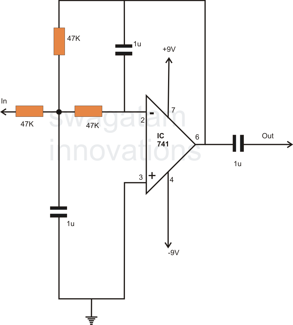
In summary, the choice between passive and active filters depends on the specific requirements of the application, including factors such as size, power consumption, and performance characteristics. The understanding of frequency behavior and the design of these filter circuits is essential for optimizing electronic systems across various fields.In electronics, filter circuits are basically employed for restricting the passage of a certain frequency range while allowing some other band offrequencyinto the further stages of the circuit. A high pass filter circuit will allow only the frequencies which are higher than thepreferredset range of frequency while a band pass filter will allow only anintermediateband of frequencies to flow to the
next stage, inhibiting all frequencieswhichmay be outside this set range of oscillations. Passive type filter are less efficient and involve complicated inductor and capacitor networks, making the unit bulky andundesirable. However these willnot requireany power requirement for itself to operate, a benefit too small to be considered really useful.
Contrary to this active type of filters are very efficient, can be optimized to the point and are less complicated in terms ofcomponentcount and calculations. The resistors and the capacitors are discretely dimensioned for a 50 Hz cut OFF, meaning no frequency above 50 Hz will be allowed to pass through the circuit into the output.
🔗 External reference
Related Circuits
This is an example of a simple inverter that can be used to power a fluorescent lamp and a small strobe. This circuit will produce over 400 VDC from a 12 VDC, 2.5 A. The described inverter circuit is designed...
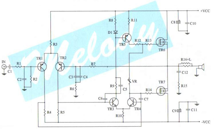
The schematic diagram of a 100-watt audio amplifier utilizing MOSFET technology. A comprehensive collection of electronic circuit diagrams is available, including a 100W RMS amplifier and a 0-30V stabilized variable power supply with current control. The 100-watt audio amplifier schematic...
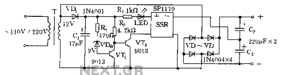
The circuit is automatically converted to a low-voltage configuration. A 220V AC supply is stepped down by transformer T. After this, the breakdown voltage of diode VDw causes transistors VT1 and VT2 to turn off, resulting in the solid-state...
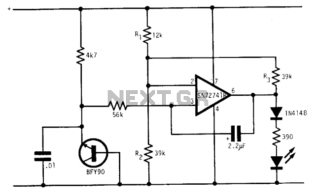
Under optimal battery conditions, the LED remains off. As the battery voltage decreases, the LED starts to flash, and when the battery reaches a low voltage condition, the LED illuminates continuously. This circuit is designed for use with a...
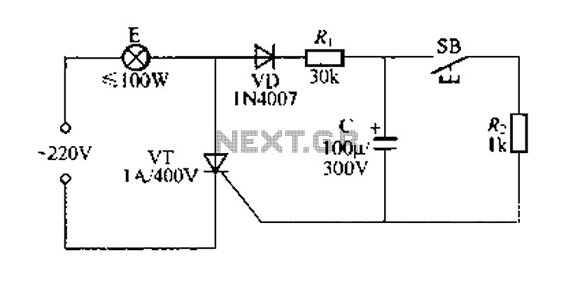
Figure 57 illustrates a simple delay lamp circuit that connects to lamp E using a two-wire connection. This design allows for the security bars to be installed directly, enabling replacement with a standard wall switch without altering the existing...
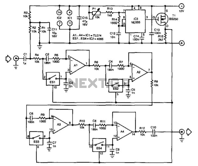
One of the challenges in designing higher-order tunable bandpass filters is achieving proper tracking of the variable resistors in the RC networks. The implementation of switched capacitor networks can resolve this issue, as demonstrated in this filter. The filter...