
Active Low-Pass Rc Filter Circuit
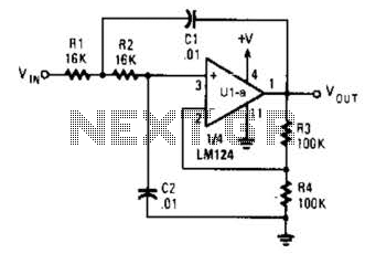
The circuit is designed as a filter, likely a low-pass or high-pass filter, where the cutoff frequency is determined by the values of the resistors and capacitors involved. The cutoff frequency (fc) can be calculated using the formula:
fc = 1 / (2πRC)
where R is the equivalent resistance and C is the equivalent capacitance in the circuit. By varying the values of R1, R2, C1, and C2, the cutoff frequency can be modified to meet specific application requirements.
For instance, if a lower cutoff frequency is desired, the values of R1 and R2 can be increased, or the values of C1 and C2 can be increased. Conversely, to achieve a higher cutoff frequency, the resistor values can be decreased or the capacitor values can be reduced.
In practical applications, this flexibility allows the circuit to be tailored for various tasks such as audio signal processing, where specific frequency ranges need to be filtered out or allowed through. The circuit may also include additional components such as operational amplifiers for signal conditioning, or diodes for protection against voltage spikes, depending on the complexity and requirements of the overall design.
The layout of the circuit should be carefully considered to minimize parasitic capacitance and inductance, which can affect the performance at higher frequencies. Proper grounding and shielding techniques should also be employed to ensure signal integrity.
In summary, this circuit's design provides a versatile solution for frequency filtering, with the ability to adjust component values to achieve the desired cutoff frequency, making it suitable for a wide range of electronic applications. The circuit shown has a cutoff frequency at about 1 kHz. Rl, R2, CI, and C2 can be scaled to change this to any other desired frequency. 🔗 External reference
Related Circuits
The circuit features an adjustable prestage utilizing the AF279 transistor, while the natural oscillation mixer stage employs the AF280 transistor. The power circuit is mounted on a board with copper coating. The main coil specifications are as follows: L1,...
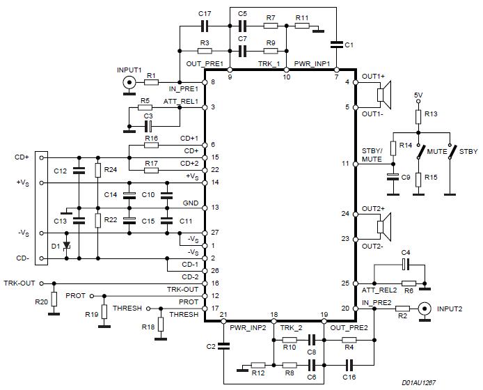
The Stereo Power Amplifier utilizes a 2x70Watt STA550 chip designed for audio power applications, featuring a BASH concept that allows connection to digital devices. This amplifier operates on a BTL (Bridge-Tied Load) system with a symmetrical power supply that...
This radio receiver can operate with any of the following transistors: ZN414, MK484, or TA7642. The radio receiver circuit is designed to utilize a variety of transistors, specifically the ZN414, MK484, and TA7642, which are commonly used in low-power AM...

The Saver V5.0 operates a simple clock emulation program that controls a night light to turn on and off at preset times, specifically from 19:00 to 22:00 daily. This design is characterized by its low cost, easy installation, lack...
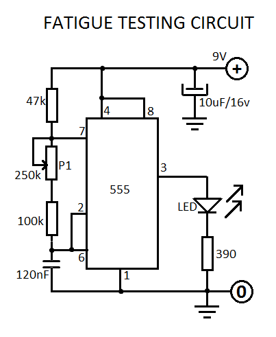
This fatigue testing circuit is straightforward and easy to assemble, designed to assess an individual's level of fatigue. Research indicates that the highest light frequency can be used as an indicator. This fatigue testing circuit operates on the principle of...
A DIY GSM jammer schematic diagram designed for use with GSM1900, operating within the frequency range of 1930 MHz to 1990 MHz. The GSM jammer circuit is intended to disrupt communication between mobile phones and base stations within the specified...