
Transistors UHF tuner circuit
The circuit design incorporates a key adjustable prestage that enhances signal processing capabilities. The AF279 transistor is selected for its high-frequency performance, enabling efficient amplification of weak signals before they are mixed in the subsequent stage. The natural oscillation mixer stage, utilizing the AF280 transistor, facilitates the combination of the amplified signal with a local oscillator signal, producing an intermediate frequency that can be further processed.
The power circuit's copper-coated board not only provides a robust substrate for the components but also aids in effective thermal management and signal integrity. The choice of eight turns for coils L1, L3, L8, and L9, using 0.35mm copper enameled wire, is critical for achieving the desired inductance values while maintaining physical compactness. The 3mm diameter of the coils allows for adequate spacing and minimizes parasitic capacitance, which can adversely affect circuit performance.
Coil L2, with three turns, is likely designed for a specific function, possibly serving as a coupling or feedback element. Coils L10 and L11, each with fifteen turns, may be configured to enhance selectivity or improve impedance matching within the circuit, contributing to overall efficiency and performance. This configuration of coils is essential for optimizing the circuit's response across its operational frequency range, ensuring reliable and effective signal processing.In the circuit, the adjustable prestage is composed of transistor AF279, and the natural oscillation mixer stage consists of transistor AF280. The power circuit is installed on the board with copper coating. The main coil data:L1, L3, L8, L9: eight turns, the coil uses 0.35mm copper enameled wire with diameter in 3mm;L2 : 3 turns, L10 : 15 turns, L11: 15 tur..
🔗 External reference
Related Circuits
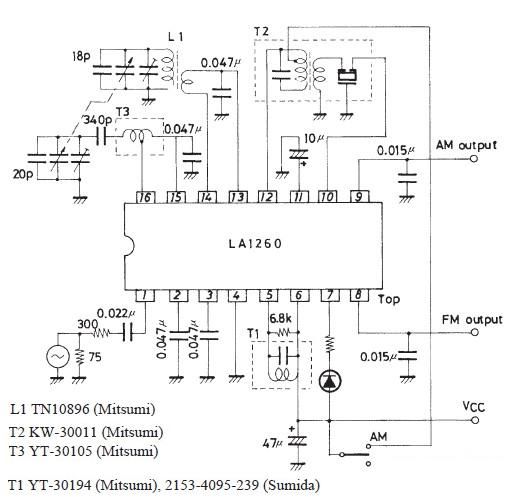
This FM IF MW radio receiver circuit schematic utilizes the LA1260 integrated circuit (IC), which is suitable for AM and FM radio receiver electronic projects. The LA1260 incorporates numerous functions and features essential for radio receiver applications, including a...
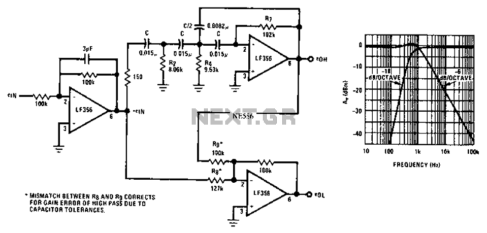
Asymmetric third-order Butterworth active crossover network circuit diagram. The asymmetric third-order Butterworth active crossover network is a sophisticated circuit designed to split an audio signal into two separate frequency bands, typically for use in multi-way speaker systems. This type of...

A hydrophone is a device similar to a microphone, designed specifically for use in underwater environments. When utilized to capture sound in air, its effectiveness diminishes. A hydrophone operates by converting sound waves into electrical signals, making it an essential...
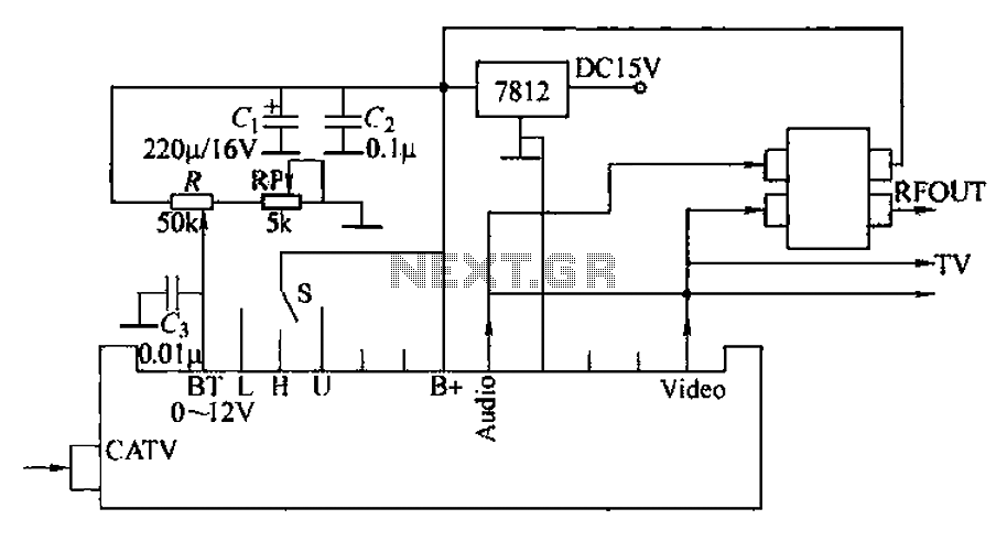
The circuit utilizes two main components: an integrated electronic tuner with AV output, commonly referred to as the tuner, which can receive CATV full channel TV signals and output a video signal (Vttko) along with an audio signal (Audio)....

This article outlines a lighting circuit designed to create a glowing firebox effect while providing constant illumination for classification lamps and an interior cab light. It includes comprehensive information necessary for constructing the circuit, such as a detailed schematic,...

This design circuit is intended for sine wave oscillators, providing both sine and square wave outputs across a frequency range from below 20 Hz to above 20 KHz. The oscillation frequency can be easily adjusted by changing a single...