
Sound Reactive EL Panel Dimmer

The sound-reactive EL panel dimmer circuit consists of several key components working in tandem to achieve the desired visual effect. The microphone (M1) captures the audio input, which is then fed into a non-inverting amplifier. This amplifier is designed with adjustable gain to accommodate varying audio levels, ensuring that the signal is appropriately amplified before further processing. Following amplification, the audio signal is routed through a low-pass filter (LPF) to eliminate high-frequency noise, allowing only the desired low-frequency audio components to pass through.
The envelope follower then processes the filtered signal, producing an output voltage that corresponds to the amplitude of the incoming audio signal. This output voltage is critical for controlling the brightness of the EL panel. The EL panel itself operates at high voltage, typically around 100V AC, which requires a transformer to step up the voltage from the power supply.
To manage the power requirements, a 5V regulator is employed to stabilize the voltage supplied to the audio processing stages. This is essential to prevent interference from the EL transformer, which operates at a frequency of approximately 2kHz and can introduce noise into the audio signal if both systems share the same power source. By isolating the audio processing from the higher voltage EL panel circuitry, the integrity of the audio signal is preserved.
The power switch, rated for 100mA, is strategically placed to control the circuit's ground connection. When activated, it allows a small current to flow through a resistor (R16) that keeps a transistor (Q4) in the "on" state, effectively connecting the circuit ground to the negative terminal of the battery. This design choice mitigates the risk of static discharge, which can occur when a circuit is disconnected from ground, particularly in battery-powered applications.
In summary, the sound-reactive EL panel dimmer is a sophisticated circuit that integrates audio signal processing with high-voltage EL panel operation. The careful consideration of component selection, voltage regulation, and signal integrity ensures that the final product meets the desired performance criteria while also providing valuable insights into the challenges faced during its development.Let me tell you a tale. 8 months and 18 days ago, on March 25, I was sent an email requesting a commissioned piece of electronic clothing similar to my DJ jacket for a musical performer to wear on stage. I mulled it over for a bit, and came up with the idea of a sound-reactive EL panel dimmer. Unlike most cheap "sound reactive" stuff that just bli nks to music, I wanted my dimmer to allow for a more appealing pulsating effect. EL panels are just like EL wire except instead of having a phosphorescent insulating tube wrapped around the inner wire in a coaxial pair, it has a sheet of the same material placed between two conductive sheets. They operate on the same principle: need 100V-ish AC input at EL wires, panels, and other materials don`t seem to be generally well understood by the sources provided to me by the internet.
I couldn`t find any good sources explaining how to make a dimmer, so I set out into uncharted water to come up with my own solution. Almost two months after that email, I had created my first sound-reactive EL panel dimmer. While it was probably one of the most educational projects I`ve worked on, it was also the biggest disaster I`ve ever blogged about.
The dimmer didn`t work very well. The panel wasn`t getting bright enough. I decided not to mail the dimmer to my client and instead try to figure out how to improve it (note the FAQ where it says that I don`t work well with deadlines). Since then, I`ve been writing a ton of posts detailing my experiments with EL wire: 1, 2, 3, 4, 5, 6, 7.
Well, I think I FINALLY HAVE IT! Okay, it`s not perfect. There were numerous ugly reworks required to make this work, and it still has some room for improvement, but as a proof of concept, it is totally done. I will probably only need one more short blog post after this to just show off a rebuilt version without all those ugly reworks.
Though I did finally get a working product, it was only after a number of changes that I had to be made along the way. In this post, I plan to not only outline how the final thing works but also describe what mistakes I made and what I learned from them.
When I designed this thing, I was concerned that my power switch couldn`t handle the current draw of the EL panel. It`s a pretty small switch and it`s only rated for 100mA. With this configuration, the switch will only need to supply the small amount of current through R16 required to keep Q4 on which connects the circuit ground to the battery`s negative terminal.
When the switch is off, no current flows anywhere. It`s typically a bad idea to disconnect a circuit from ground as you can have static discharge issues, but with battery power, this thing will never really be "grounded" anyway. The audio signal starts at M1 (the microphone), gets amplified through a non-inverting amplifier with adjustable gain, passed through a LPF, and then an envelope follower.
This should generate an output signal that is proportional in voltage to the amplitude of the audio coming into it. At least the amplitude of the audio content under 50Hz or so. Here`s a trace of the audio signal going to the envelope follower and the signal coming out: This is ripped ripped right out of my other audio projects, so you might be able to find a more in-depth description here.
The only difference this time is that I`m using a 5V source rather than driving it straight off the 9V battery. The EL transformer stage draws a significant sinusoidal current from the battery at about 2kHz, and this can easily couple its way into an audio gain stage running off the same source and cause interference.
This is what happened with my latest pair of shutter shades. The 5V regulator will output a very stable 5V regardless of noise on the 9V rail, so running all of the audio stages off the 5V supply should reduce interference. The microphone is a small condenser mic which means the same line powers it and carries the audio signal away from it.
🔗 External reference
Related Circuits
Savings on electricity bills can be achieved by utilizing alternative power sources. The photovoltaic module or solar panel described here has a power output of 5 watts, providing 16.5V under full sunlight conditions, with a current delivery of 300-350...
A useful operation for the cars is delayed extinguishing internal lighting cabin of passengers, after close some door of car. Certain cars allocate this operation from their constructor. Oldest sure do not allocate such operation. This delay makes this...
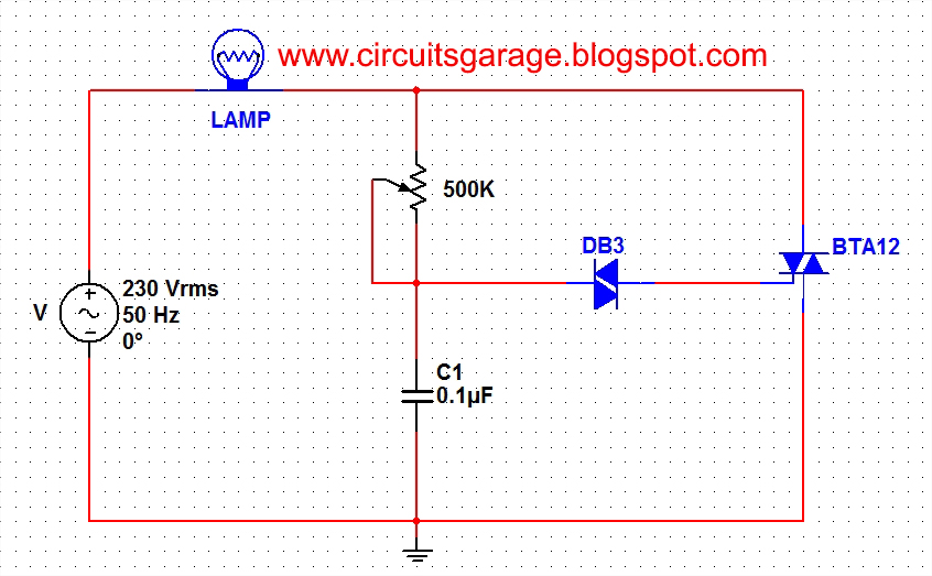
A light dimmer circuit is used to adjust the illumination of a lamp. The following circuit illustrates a basic TRIAC triggering circuit that utilizes a DIAC. In this circuit, the illumination of the light is regulated through the interaction...
The Z86E02 is one of ZiLOG's most popular Z8 One Time Programmables (OTPs). It features a 512-byte EPROM, 61 bytes of RAM, 14 I/O ports, a Watch-Dog Timer, Power-On Reset, a Low-Voltage Protection circuit, and an additional Timer. Notable...
The USB sound card circuit utilizes the PCM2702 integrated circuit (IC) to create a fully functional USB sound card. The design is straightforward, allowing for the easy implementation of audio processing capabilities. The PCM2702 is a versatile USB audio controller...
A dimmer for individual LED bulbs. LEDs (light emitting diodes) are very sensitive components; exceeding their rated current or voltage can drastically reduce their lifespan from over 50,000 hours to mere microseconds. LEDs are current-driven, meaning that the intensity...