
AD2S80A typical connection circuit
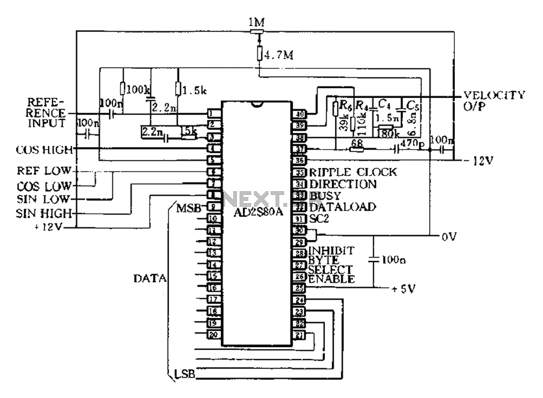
The AD2S80A is a high-performance resolver-to-digital converter (RDC) designed for precise angular position measurement in various applications, including robotics and industrial automation. The device operates with a 12-bit resolution, allowing for fine granularity in position tracking. The reference frequency of 5 kHz is optimal for many dynamic applications, providing a good balance between responsiveness and signal integrity.
The specified bandwidth of 520 Hz indicates the frequency range over which the RDC can accurately track changes in position. This is crucial in high-speed applications where rapid changes in position must be monitored without lag. The maximum tracking speed of 260 R/s ensures that the system can handle fast movements, making it suitable for applications that require quick adjustments and high precision.
The static and uniform operation of the RDC ensures that under stable conditions, the system can maintain accurate readings without introducing errors. This characteristic is essential for applications where consistent performance is critical. However, it is important to note that during acceleration, additional positional errors can arise. These errors can be quantified through the converter's acceleration factor, KA, which relates the rate of change in position to the resulting angle error. Understanding this relationship is vital for engineers when designing systems that require high precision in dynamic conditions.
Incorporating the AD2S80A into a system involves careful consideration of the peripheral connectivity, ensuring that the device interfaces correctly with other components such as microcontrollers or digital signal processors. Proper implementation of the device parameters is essential for achieving optimal performance and minimizing errors in position tracking, particularly in applications that involve rapid acceleration or deceleration.AD2S80A represents a typical application circuit, give a specific peripheral connectivity and device parameters. As illustrated, it is provided 12bit (SCl-0, Sc2 1), to select the reference frequency 5kHz. Bandwidth is 520Hz, maximum tracking speed 260R/s. As described above, since the tracking type servo loop RDC is l, static and uniform work, the position and velocity without introducing errors. But when accelerating position will produce additional errors. This additional angle error is determined by the converter acceleration factor KA.
Related Circuits
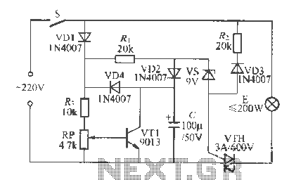
Using high-beam headlights while driving on the highway can significantly enhance visibility; however, they may pose a blinding risk to other drivers. This straightforward circuit can be integrated into the headlight switch to enable automatic switching between high and...
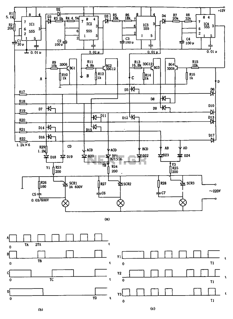
The decorative lamp control circuit is illustrated in the figure. The controller comprises a pulse generator, a frequency divider, a matrix circuit, and a thyristor control circuit. Components IC1, R1, R2, C1, and others form a multivibrator where the...
This is a type of connection switch designed for incandescent lamps, known as a spider life extension switch. It has two main functions: First, it utilizes electroporation to enable semi-crossing buck starts and fully preheats the filament to transfer...
Here is an amplifier circuit based on the BUZ11, which can be replaced by an IRFZ34N, and an ECC83 can be used instead of the ECC88. In this case, the anode voltage should be reduced slightly to 155 V....
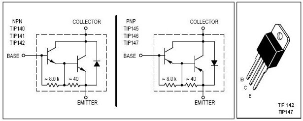
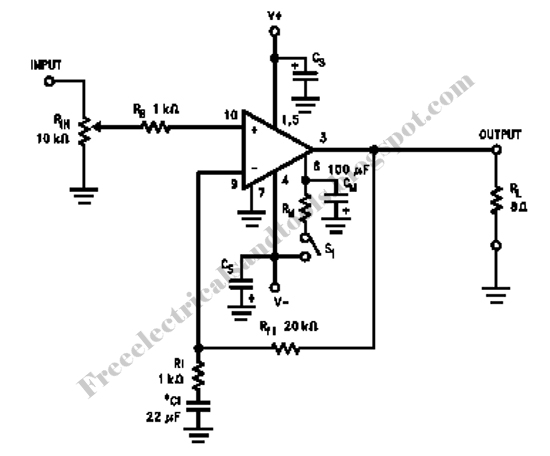
This is an economical 150 Watt amplifier circuit featuring two Darlington power transistors, TIP 142 and TIP 147. The circuit is capable of delivering up to 150 W RMS to a 4 Ohm speaker, providing substantial audio output. The...
This is an FSK modulation circuit composed of the 74LS74. The FSK modulation circuit does not include a phase-locked loop (PLL) or a high-Q bandpass filter, eliminating the need for tuning adjustments in the high-frequency modulation circuit. The two...