
Simple Hybrid Audio Amplifier Circuit
The described amplifier circuit utilizes a BUZ11 MOSFET, which serves as the primary amplification component. This device can be substituted with an IRFZ34N MOSFET, offering similar performance characteristics. The ECC83 vacuum tube, also known as the 12AX7 in the United States, is a dual triode that can replace the ECC88 tube in this configuration.
When using the ECC83, it is critical to adjust the anode voltage to approximately 155 V to ensure optimal performance and prevent damage to the tube. The ECC83 requires a specific operating voltage and current to function effectively, typically drawing around 2 mA per triode section.
In the circuit design, the input stage can be configured to handle low-level audio signals, which are then amplified by the ECC83 before being fed into the MOSFET stage for further amplification. The output stage, driven by the MOSFET, provides the necessary power to drive speakers or other loads, ensuring that the amplifier can deliver the required output without distortion.
Proper biasing of the ECC83 is essential for achieving linear amplification and minimizing distortion. This can be accomplished through a resistor network that sets the appropriate gate voltage for the MOSFET, ensuring that it operates within its linear region. Additionally, coupling capacitors may be employed at the input and output stages to block DC voltage while allowing AC signals to pass through.
Overall, this amplifier circuit design offers flexibility through component substitutions while maintaining performance integrity, making it suitable for various audio amplification applications.Here s an amplifier circuit that based on the BUZ11 can be replaced by an IRFZ34N and an ECC83 can be used instead of the ECC88. In that case the anode voltage should be reduced slightly to 155 V. The ECC83 (or its US equivalent the 12AX7) requires 2 .. 🔗 External reference
Related Circuits
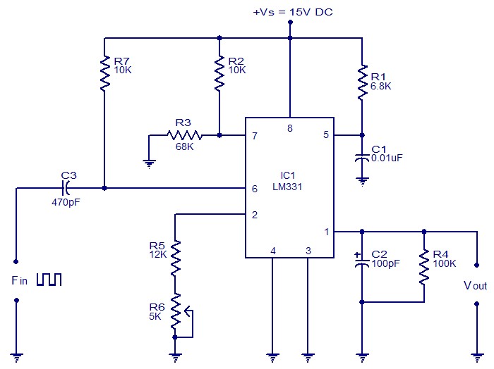
The following circuit illustrates a Frequency Voltage Converter Circuit. This circuit is based on the LM331 IC and operates with a supply voltage of 15V DC. The Frequency Voltage Converter Circuit utilizes the LM331 integrated circuit, which is designed for...
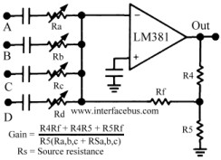
The circuit schematic below represents a method for designing an audio mixer. The active component is an LM318, although any operational amplifier could be used in its place. The circuit is a classic design for an operational amplifier summing...
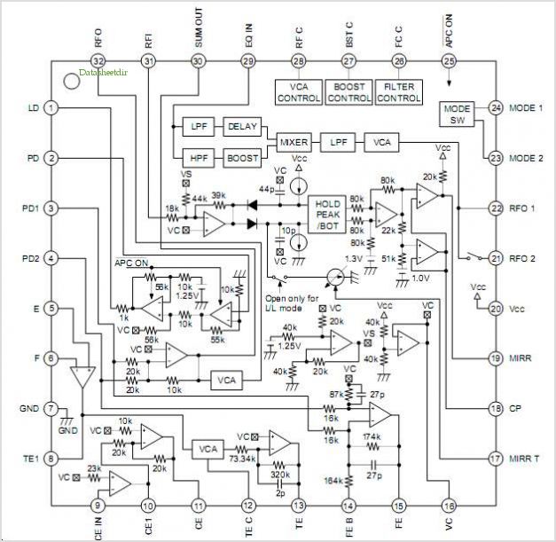
The CXG1024N is a high-power antenna switch MMIC designed to connect a transmitter/receiver (TX/RX) to one of four antennas. This integrated circuit (IC) is fabricated using Sony's GaAs J-FET process and operates with a single positive power supply. The CXG1024N...
A DIY GSM jammer schematic diagram designed specifically for GSM1900 frequencies ranging from 1930 MHz to 1990 MHz. The GSM1900 mobile phone network is utilized in the USA, Canada, and most South American countries. This cell phone jammer is...
The 60 Hz frequency generator circuit is essential for creating inverters or hardware related to AC current voltage. This 60 Hz frequency generator is straightforward and highly accurate, producing a precision square wave output. The core of this generator...
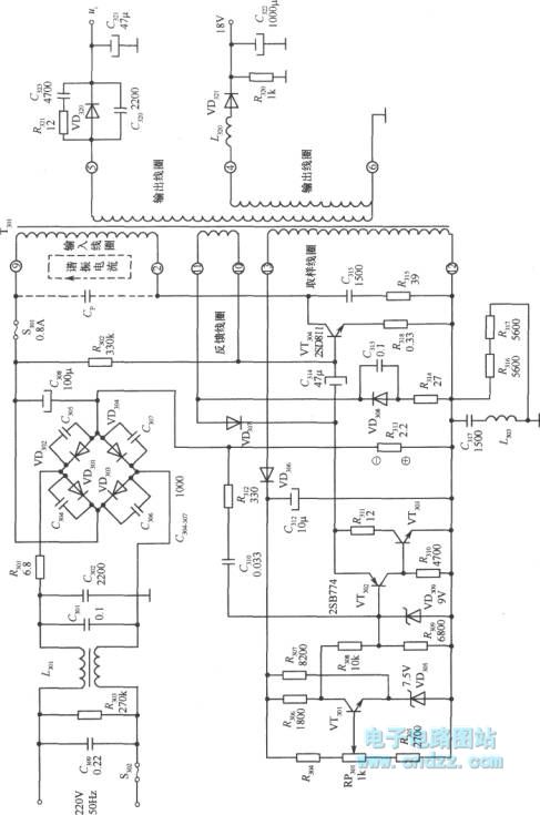
A high voltage switching stabilized voltage supply circuit is illustrated in the diagram. This is the switching power supply for an 80P type color television. It utilizes auto-excitation and a PWM circuit. The output is isolated from the power...