
150 Watt amplifier circuit
The 1.2 X 60 Watts stereo amplifier circuit utilizes the LM4780 audio amplifier IC, which can provide 60 Watts RMS output power per channel to 8 Ohm speakers. The advantages of this IC include low harmonic distortion compared to other similar amplifiers and a power supply rejection rate of 85 dB. It requires minimal components and features a built-in mute function.
Additionally, a headphone amplifier circuit is described, which comprises only three transistors and can effectively drive headphones. It is simple to construct and can be powered by a 3-volt battery.
Another design is a MOSFET amplifier circuit, which uses two MOSFETs and one transistor, allowing for easy assembly. This circuit can deliver 18 Watts to an 8 Ohm speaker or 30 Watts to a 4 Ohm speaker, with minimal components required.
A 40 Watts amplifier circuit using the TDA1514 IC from Philips is also presented. This high-performance Hi-Fi amplifier requires a dual ±25 volts power supply and offers low total harmonic distortion (THD), a mute standby feature, and thermal protection. It can output 40 Watts to an 8 Ohm speaker, necessitating a proper heat sink for reliability.
Lastly, a 2 X 32 Watts stereo amplifier circuit is constructed using two TDA2050 ICs, each providing 32 Watts in a Class AB configuration. This setup includes features like thermal shutdown, low THD, and short circuit protection, powered by an 18 volts dual power supply.
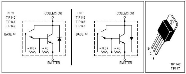
For further inquiries regarding article content, copyright issues, or other concerns, communication can be directed to the provided email address within 15 days for resolution.This is the cheapest 150 Watt amplifier circuit you can get, I think. Based on two Darlington power transistors TIP 142 and TIP 147, this circuit can deliver a blasting 150 W Rms to a 4 Ohm speaker. Enough for you to get rocked, then try out this. TIP 147 and 142 are complementary Darlington pair transistors which can handle 5 A current and 100V, fam
ous for their ruggedness. Here two BC 558 transistorsQ5 and Q6 are wired as pre amplifier and TIP 142, TIP 147 together with TIP41 (Q1, Q2, Q3) for driving the speaker. This circuit is designed so rugged that this can be assembled even on a perf board or even by pin to pin soldering.
The circuit can be powered from a /-45V 5A dual power supply. You must try this circuit. Its working great. The preamplifier section of this circuit is based around Q4 and Q5 which forms a differential amplifier. The use of a differential amplifier in the input stage reduces noise and also provides a means for applying negative feedback.
Thus overall performance of the amplifier is improved. Input signal is applied to the base of Q5 through the DC decoupling capacitor C2. Feedback voltage is applied to the base of Q4 from the junction of 0. 33 ohm resistors through the 22K resistor. A complementary Class AB push-pull stage is built around the transistors Q1 and Q2 for driving the loud speaker. Diodes D1 and D2 biases the complementary pair and ensures Class AB operation. Transistor Q3 drives the push-pull pair and its base is directly coupled to the collector of Q5. 1. 2 X 60 Watts Stereo Amplifier Circuit is designed using LM4780, an audio amplifier IC that can deliver 60 Watt RMS output power per channel to 8 Ohms speakers.
Advantages of using this IC are low harmonic distortion compared to other IC amplifiers of similar category and a power supply rejection rate of 85db. In addition it require minimum components and a built in mute function. 2. Headphone Amplifier Circuit This is a simple circuit which uses only 3 transistors, that can be used to drive your headphone.
It can be easily built by any one and can be powered using a 3 volts battery. 3. Mosfet Amplifier Circuit -This circuit is designed using two Mosfet`s and one transistor; which makes it an easy to build circuit. It can deliver 18 Watts output power to 8 ohms speaker or 30 watts to 4 ohms speaker; you can do it the way you like it.
Another advantage of this circuit is the minimal use of components. 4. 40 Watts Amplifier using TDA1514 -TDA1514 is a high performance hi fi amplifier from Philips. It requires a dual 25/-25 volts supply. Advantages of using TDA1514 are low THD, mute standby feature, thermal protection and other features. It can deliver 40 watts of output power to an 8 ohm speaker. You need a proper heat sink for the desired reliability of this circuit. 5. 2 X 32 Watts Stereo Amplifier Circuit This circuit is built using TDA2050 which is a 32 Watts Class AB Audio amplifier IC (monolithic).
This IC has many features like thermal shut down, low THD, short circuit protection etc. This circuit uses Two of these IC TDA205o; one for each channel. An 18 volts dual power supply is required to power this circuit. We aim to transmit more information by carrying articles. Please send us an E-mail to wanghuali@hqew. net within 15 days if we are involved in the problems of article content, copyright or other problems. We will delete it soon. 🔗 External reference
Related Circuits
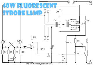
This circuit is designed for a 40 Watt fluorescent lamp. It operates similarly to a traditional strobe light, but utilizes a fluorescent tube instead. The fluorescent tube remains continuously energized, with both electrodes supplied with electricity. This current causes...
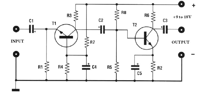
The amplification of this preamplifier is very high. To reduce the amplification, a trimmer resistor R3 in series with a value of 100 ohms should be used. The system can be powered by a voltage ranging from 9 to...
The output devices are MJL4281A (NPN) and MJL4302A (PNP), and feature high bandwidth, excellent SOA (safe operating area), high linearity and high gain. Driver transistors are MJE15034 (NPN) and MJE15035 (PNP). All devices are rated at 350V, with the power...
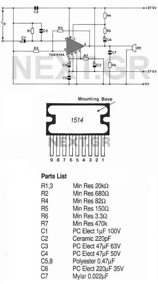
This high-quality audio amplifier is based on the TDA1514A, a 9-pin flat package integrated circuit. The heatsink must be insulated from the ground. The amplifier can deliver 40 watts into an 8-ohm load with a 27.5-volt power rail or...
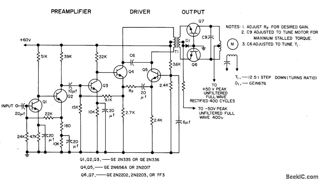
The circuit is capable of driving a 3W servo motor in an ambient temperature range of -55 to 125 degrees Fahrenheit, provided that capacitors rated for 125 degrees Fahrenheit are utilized. The gain can be adjusted over a range...
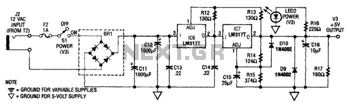
The power supply presented is intended to function with a wall transformer. This circuit can be utilized alongside a variable supply for testing circuits in a laboratory setting. T2 serves as a 12-V wall transformer. The power supply circuit is...