
Adaptor for 8 and 28 pin AVR
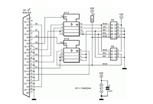
The described adaptor functions as a versatile interface for programming both 8-pin and 20-pin Dual In-line Package (DIP) devices using an In-System Programmer (ISP) in accordance with Atmel's AVR910 application note. The circuit is designed to supply the necessary power and clock signals to the target microcontroller while simultaneously powering the ISP.
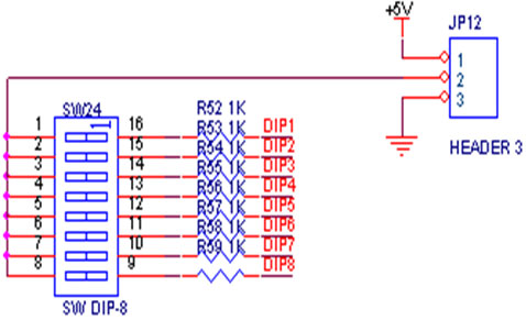
In the 8-pin configuration, the device is aligned such that its pins correspond to specific positions on the programming socket. The 8 pins of the microcontroller connect to pins 1, 2, 3, 4, 17, 18, 19, and 20 of the socket. This arrangement ensures that the programming signals are correctly routed to the appropriate pins of the microcontroller. An important feature of this design is the inclusion of a Single Pole Single Throw (SPST) switch connected to pin 4. When programming an 8-pin device, the switch must be closed to ground pin 4, which is critical for proper operation during programming.
In contrast, when programming a 20-pin device, the circuit configuration changes. The same SPST switch must be opened to allow the oscillator crystal to function as the clock source for the target microcontroller. This change is essential as the 20-pin devices require the clock signal to be sourced from the crystal oscillator, ensuring accurate timing during the programming process.
The circuit likely includes additional components such as decoupling capacitors to stabilize the power supply, resistors for pull-up or pull-down functions, and possibly indicators like LEDs to show the status of the programming operation. Proper attention to layout and signal integrity is crucial to avoid issues during programming, especially considering the differing requirements of the two configurations.
Overall, this adaptor provides a practical solution for programming both 8-pin and 20-pin DIP devices, facilitating development and testing in embedded systems using Atmel microcontrollers.This adaptor lets me program 8 or 20 pin DIP devices using the In-System Programmer (ISP) described in Atmel's AVR910 application note. This circuit provides power and clocks for the part to be programmed and power to the ISP circuit. When programming 8 pin devices, the part is positioned toward pins 1 and 20 of the socket such that the 8 pins of the chip occupy the pins 1,2,3,4,17,18,19, abd 20 of the programming socket.In the case of an 8 pin part being programmed, the SPST switch that grounds pin 4 must to be closed.
Conversely, when programming a 20 pint part, the switch on pin 4 must be open so the crystal can be used for the clock for the part being programmed. 🔗 External reference
Related Circuits
A switch is an electrical component that can break an electrical circuit, interrupting the current or diverting it from one conductor to another. A switch may be directly manipulated by a human as a control signal to a system...
The Supertex HV440 is utilized for creating a pulse width modulated high voltage ring generator in telecommunication applications. The HV440 can function in both closed-loop and open-loop configurations. A closed-loop design, while more intricate, offers improved load regulation and...
An Xbox controller rapid fire modification requires a chip that can send a ground signal quickly to a specific point. The desired solution should replace a previously used 555 timer due to its size. The project necessitates a microcontroller...
This circuit is designed to program AVR controllers, specifically the AT90S1200, using a parallel port. The circuit is very straightforward. IC1 serves as a buffer. The circuit operates by interfacing the parallel port of a computer with the AVR microcontroller....
Development board for 18-pin PIC microcontrollers featuring a power supply circuit, crystal oscillator circuit, RS232 port, ICSP/ICD port, 4 relay outputs, and 4 optocoupler isolated inputs. This development board is designed to facilitate the prototyping and testing of applications utilizing 18-pin...

This project involves the DiSEqC-Tester, which is designed to test DiSEqC switches utilizing protocols 1.0 and 1.1. The device is compatible with DiSEqC switches that follow protocols 2.0 and 2.1, as they maintain backward compatibility with the earlier versions....
Warning: include(partials/cookie-banner.php): Failed to open stream: Permission denied in /var/www/html/nextgr/view-circuit.php on line 713
Warning: include(): Failed opening 'partials/cookie-banner.php' for inclusion (include_path='.:/usr/share/php') in /var/www/html/nextgr/view-circuit.php on line 713