
digital inputs interfacing with avr primer
A switch is a fundamental component in electronic circuits, acting as a gatekeeper for electrical current. In the context of microcontroller applications, switches are essential for input control, allowing users to interact with the system. The typical implementation involves connecting a switch to a microcontroller's digital input pin, where the state of the switch (open or closed) translates to a high or low voltage level.
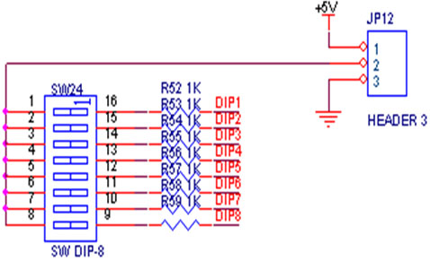
To ensure that the microcontroller reliably detects these states, pull-up or pull-down resistors are employed. A pull-up resistor connects the input pin to the supply voltage, ensuring that when the switch is open, the pin reads a high voltage. Conversely, when the switch is closed, the pin is connected to ground, resulting in a low voltage reading. This configuration is critical for maintaining stable and predictable input signals for the microcontroller.
In the specific application with the AVR Primer Board, eight LEDs are controlled via eight switches, all interfaced through PORTB. The LEDs are activated by setting the corresponding port pins high, while the switches provide the necessary input to toggle these states. The interaction is straightforward: pressing a switch will turn on an LED, while releasing it will turn the LED off, depending on the switch's designed logic level.
The development environment for this project is facilitated by CodeVision AVR software, which streamlines the process of writing, compiling, and debugging code for AVR microcontrollers. The built-in AVR GCC compiler allows for efficient code compilation, generating a HEX file that can be uploaded to the microcontroller. The IDE supports project management, enabling developers to organize their files and settings effectively. Debugging features allow for simulation of the code's behavior, making it possible to test the logic without physical hardware, which is particularly useful for troubleshooting and verifying code functionality.
In summary, the integration of switches and LEDs in an AVR microcontroller project exemplifies a practical application of electronic principles, showcasing the importance of input control and the role of software tools in developing embedded systems.A switch is an electrical component that can break an electrical circuit, interrupting the current or diverting it from one conductor to another. A switch may be directly manipulated by a human as a control signal to a system, or to control power flow in a circuit.
Fig. 1 shows how to interface the switch to microcontroller. A simple switch has an open state and closed state. However, a microcontroller needs to see a definite high or low voltage level at a digital input. A switch requires a pull-up or pull-down resistor to produce a definite high or low voltage when it is open or closed. A resistor placed between a digital input and the supply voltage is called a "pull-up" resistor because it normally pulls the pin`s voltage up to the supply.
We now want to control the LED by using switches (Digital-Inputs) in AVR Primer Board. It works by turning ON a LED & then turning it OFF when switch is going to LOW or HIGH respectively. The AVR Primer board has eight numbers of point LEDs, connected with I/O Port lines (PORTB. 0 PORTB. 7) to make port pins high. Eight switches, connected with I/O port lines PORTB are used to control eight LEDs. To compile the above C code you need the CodeVision AVR software. The software has it`s own IDE and built-in AVR gcc- Compiler. They must be properly installed and a project with correct settings must be created in order to compile the code. To compile the above code, the C file must be added to the project. In CodeVision AVR software, you can develop or debug the project without any hardware setup. You must compile the code for generating HEX file. In debugging Mode, you want to check the port output without microcontroller Board. If you are not reading any output signal in LED, then you just check the jumper connections. Otherwise you just check the code with debugging mode in Mplab. 🔗 External reference
Related Circuits
This circuit allows for amplifier volume control without the need for a potentiometer, utilizing an IC DS1669. The operating voltage for this type of IC ranges from 4.5 volts to 8 volts; however, in this circuit, it is used...
The circuit illustrates how to interface a Wi-Fi module with a microcontroller. The Wi-Fi module continuously transmits and receives serial data using the RS232 protocol over the internet without the need for wires. It facilitates data reception and transmission...
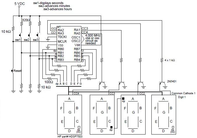
A digital clock project utilizing the PIC16C54 microcontroller can be constructed using the provided circuit diagram. This electronic project features a time-of-day clock that includes four seven-segment LED displays and three input switches. Additionally, there is a reset switch...
The ICL7107 is a 3 1/2 digit LED analog-to-digital converter (A/D converter). It features an internal voltage reference, high-isolation analog switches, sequential control logic, and display drivers. The ICL7107 is designed to convert analog signals into digital representations with a...
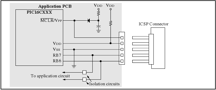
The programmer utilizes a serial signaling scheme to program the chip while it is in-circuit. The signaling is transmitted through the programming clock (PGC or ICSPCLK) and the programming data (PGD or ICSPDAT) pins. Additionally, the MCLR/VPP pin serves...

Usually we see Digital clock on LCD or 7 segment. But, this AVR Digital Clock which is designed by Ficara Emilio displayed on Oscilloscope. The project uses ATtiny 2313 as the main controller. What an interesting microcontroller project. Source...