
AVR Projects

The DiSEqC-Tester is a versatile tool for testing and generating DiSEqC messages, crucial for the operation of satellite communication systems. The device's ability to handle multiple protocols and its compatibility with various DiSEqC switch types make it an essential component for engineers and technicians working in the field of satellite technology. The integration of LEDs for visual feedback enhances usability, allowing for immediate status indications during testing.
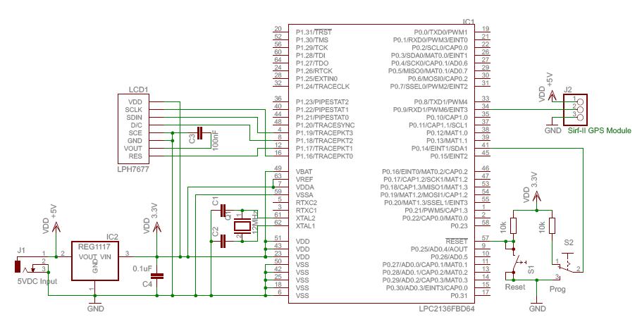
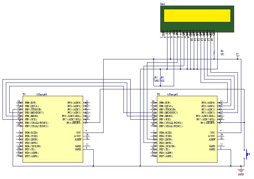
The circuitry of the DiSEqC-Tester includes a microcontroller (MCU) that manages the generation and transmission of DiSEqC messages. The MCU interfaces with a series of input and output pins, where the DIP switch configuration allows users to select between different operational modes and protocols. The inclusion of EEPROM provides storage for commonly used DiSEqC messages, enabling quick access and execution.
The design also incorporates protection features to safeguard against short circuits, ensuring the reliability of the tester during use. The option to enable a 22kHz tone adds functionality, allowing for compatibility with additional switch types that require this feature. The manual operation mode through a push button provides flexibility for users to test specific scenarios on demand.
Overall, the DiSEqC-Tester serves as a robust solution for testing and generating DiSEqC commands, facilitating the maintenance and setup of satellite reception systems. Its thoughtful design and comprehensive features make it a valuable asset for professionals in the electronics and telecommunications industry.This is my first AVR-project on this page. The DiSEqC-Tester allows to test DiSEqC-switches that uses 1. 0 or 1. 1 protocols. (DiSEqC-Switches with 2. 0 and 2. 1 protocol have backwards compatibility with 1. 0 & 1. 1 respectively and also may be tested). The device every second sends a DiSEqC-message that makes switch a DiSEqC-switch. Four LEDs are inte nded to show on/off state of ports of a DiSEqC-switch. To test a DiSEqC-switch you must connect the red wire with "Receiver" input of the switch, blue wire with case, connect remaining yellow wires to ports of the switch in any order. Choose the protocol, tone-level and then turn power on. If the DiSEqC-switch is OK, a blue LED of the tester will be switching every second to another blue LED with short red LED blinking and beeping.
Next photo and video shows how it looks. The device every second generates a DiSEqC-message which has duration of 54ms. Each message consist from 4 bytes. Byte is 8 bit + 9-th odd bit. If protocol 1. 0 is used, then device sends next commands-sequences: $E01038C0, $E01038C4, $E01038C8, $E01038CC, $E01038C0 and so later, else $E01039F0, $E01039F1, $E01039F2, $E01039F3, $E01039F0. These commands are so called "Write Port Group N0" (38h) and "Write Port Group N1" (39h) by DiSEqC-Protocol.
The full description of DiSEqC-Protocol can be found at Eutelsat web site. For example, DiSEqC-Message $E01038C0 switches port "LNB1" of DiSEqC-Switch 1. 0/2. 0 into active state. DiSEqC-Tester_T2313_rev_A - DiSEqC 1. 0 (4 ports), 1. 1 (8 porst), 1. 2 ("west", "east"). After every 4-th/8-th command - large pause (for protocols 1. 0 and 1. 1). No large pauses in 1. 2-protocol mode. The archive contains some diagrams. Number of port-LEDs may be variable, for example 8 or 10, and depends on type of your DiSEqC-Switch. In fact, this device is a DiSEqC-generator, that generates standard DiSEqC-messages. This version of tester is able to provide the 22kHz between the messages, if enabled by DIP-Switch. The DIP-Switch is intended to select protocol and mode you need. Also the DiSEqC-Tester v2 has an improved short circuit protection. Additionally, the 22kHz tone support allows you to test an 22kHz-switch. The DIP-switch allows to select DiSEqC level, type of framing byte and few other capabilities (see schematic diagram). The button is used only in manual mode, when the tester sends a message after button pressing. The DiSEqC-Converter is intended for PC DVB-cards which have not support the DiSEqC 1. 2 level. Also some cards can work poorly with DiSEqC 1. 2. The device decodes DiSEqC 1. 0 messages and sends DiSEqC 1. 2 messages to a motor. A position corresponds to a port of DiSEqC 1. 0. Four positions are possible, because it is the restriction of the DiSEqC 1. 0 level. The converter sends a message to a motor when DiSEqC 1. 0 port number is changing to another. The device can generate any DiSEqC-message. Eight DiSEqC-messages are stored in EEPROM of MCU. The length of a message can be three to six bytes. Also the generator is able to provide 22kHz tone. When 22kHz tone is used (A3=1), you can see at the diagram the pauses of 15ms before and after DiSEqC-message.
The pauses are also present when 22kHz tone is disabled (A3=0). For example: 0x04, 0xE0, 0x10, 0x38, 0xCC, 0x00, 0x00, 0x00 - DiSEqC 1. 0 message, length of the message is 4 bytes, will switch port #4 of a DiSEqC-Switch 1. 0/2. 0. The number of required DiSEqC-message is selected by pins A0. A2 of MCU. If you are using an ISP-programmer, when it is necessary to use RESET-pin during the programming, after you set RSTDSBL FUSE to zero, you`ll cannot program your MCU more, only it will be possible with a High-Voltage programmator. To prevent such situations, use the simplified solution of the DiSEqC-Generator. This version does not use RESET-pin as general in-out pin. 🔗 External reference
Related Circuits
In 1991, there was significant interest in a specific display technology that was difficult to find locally and expensive to import. Currently, this technology has become widely available and is considered obsolete due to the affordability and accessibility of...
The classic Rangemaster is considered a source of some of the finest tones in rock guitar, from Clapton's Beano sound to Brian May's singing sustain tones. Although the effect is a simple one-transistor booster, finding a high-quality germanium transistor...
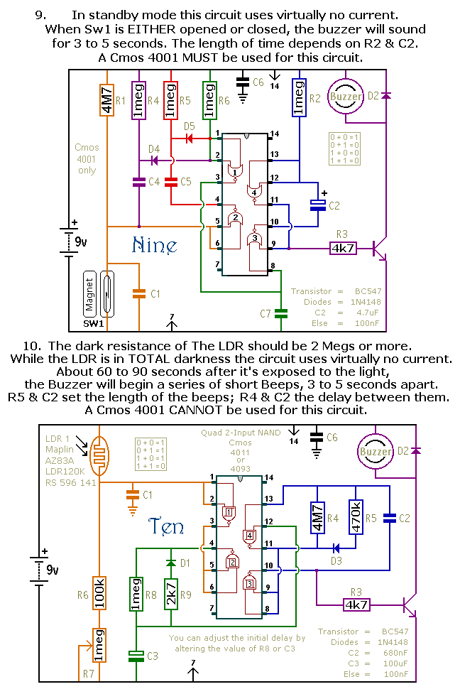
This document outlines a selection of small self-contained alarm circuits. Each alarm's main features are detailed on the circuit diagram. They are designed to have a very low standby current, making them suitable for battery operation. Each pair of...
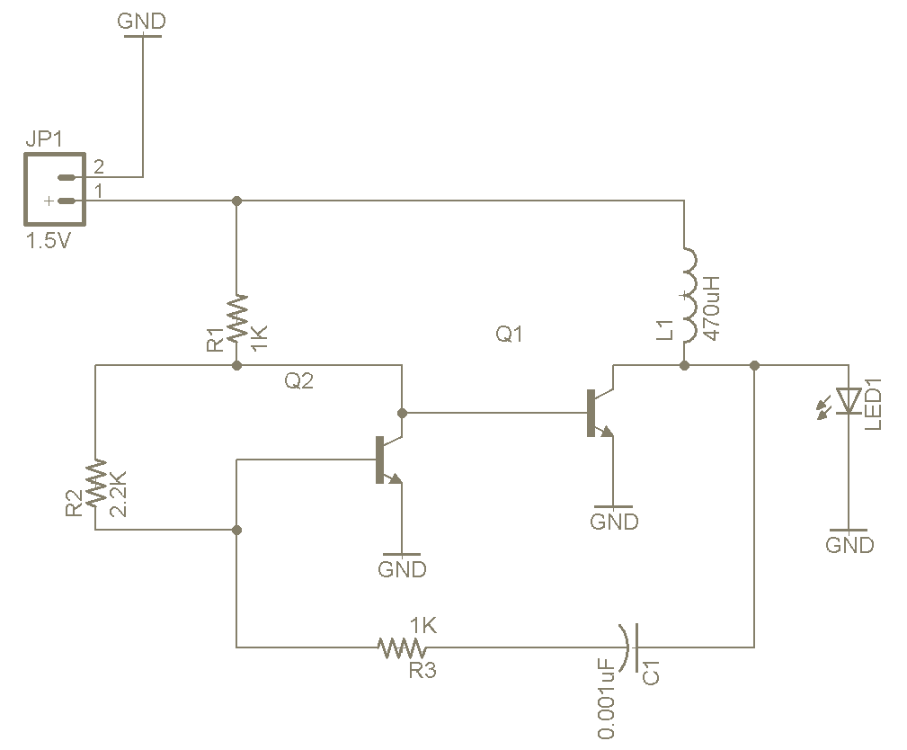
The Joule Thief is a straightforward and uncomplicated device, yet its functionality is remarkable. It can utilize a battery that is otherwise deemed unusable in any other electronic device, and it is very easy to construct on a breadboard...
SPI stands for Serial Peripheral Interface, which is the simplest among all communication protocols. Eight-bit data registers in the devices are connected by wires. These data registers function as shift registers, with one device controlling the data exchange within...
The previous section discussed several basic free-air laser light communication projects. It covered the modulation of a He-Ne laser beam using a transformer, transistor, and a piece of Mylar foil stretched in a needlepoint hoop. Various methods for electronically...