
Adc Poller Circuit
The CS5501 analog-to-digital converter employs a delta-sigma architecture, providing high-resolution signal conversion suitable for various applications. The continuous conversion mode allows for real-time signal processing; however, the lack of a start convert command necessitates a mechanism for controlled data retrieval. By integrating a dual J-K flip-flop, the circuit can be modified to enable polling, which enhances the flexibility of data acquisition.
In the asynchronous communication mode (UART), the CS5501 can efficiently transmit data over an RS-232 serial line. The use of a null character to set the flip-flop PF2 ensures that the ADC only outputs data when explicitly requested, minimizing unnecessary data transmission and power consumption. The conversion word is transmitted as two bytes, accommodating the RS-232 protocol's requirements for start and stop bits, ensuring reliable communication between devices.
The baud rate configuration, achieved through the 74HC4040 counter/divider, allows for adaptability in communication speed, ensuring compatibility with various serial communication standards. This capability is particularly advantageous in applications where the ADC's output register is utilized in synchronous-serial clock (SSC) mode. In this mode, the CS5501 can efficiently load conversion data into a serial-to-parallel register composed of two 74HC595 shift registers, enabling streamlined data handling and processing.
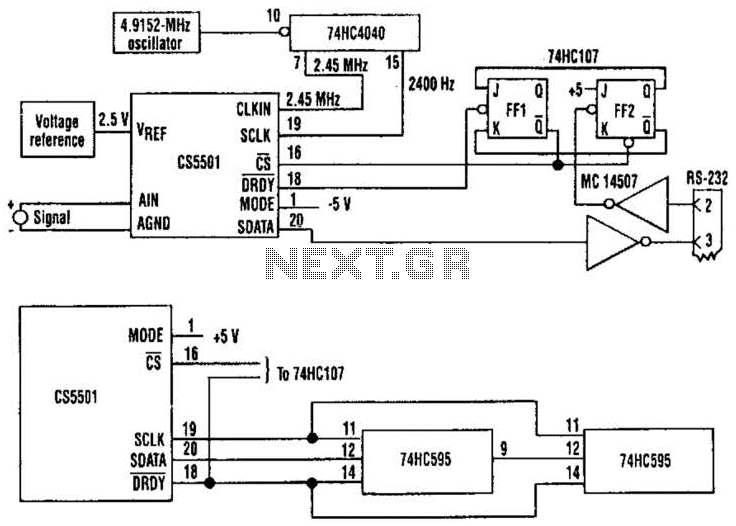
Overall, the integration of the CS5501 ADC with additional components such as the dual J-K flip-flop and 74HC4040 counter/divider provides a robust solution for precise and controlled data acquisition in digital systems. Because the CS5501 16-bit-delta-sigma analog-to-digital converter lacks a start convert command, it converts continuously, outputting conversion words to its output register every 1024 cycles of its master clock. However, by incorporating a standard dual J-K flip-flop into the circuit, the ADC can be configured to output a single-conversion word only when it is polled.The CS5501 converter can be operated in its asynchronous communication mode (UART) to transmit one 16-bit conversion word when it is polled over an RS-232 serial line (see figure).
A null character (all zeros) is transmitted to the circuit and sets the flip-flop PF2. The CS5501 can then output a single-conversion word, which is transmitted over the RS-232 line as two bytes with start and stop bits. The baud rate can be chosen by selecting the appropriate clock divider rate on the 74HC4040 counter/divider as the serial port clock (SLCK) for the ADC. This type of polled-mode operation is also useful when the ADC`s output register is configured to operate in the synchronous-serial clock (SSC) mode.
In this case, the converter will load one output word into a 16-bit serial-to-parallel register (two 74HC595 8-bit registers) when polled to do so (see figure). 🔗 External reference
Related Circuits

The TBA120 Series integrated circuits (ICs) offer a high-gain limiting intermediate frequency (IF) amplifier and a quadrature coincidence detector in a single package. These ICs are primarily designed for the extraction of television intercarrier sound, which is frequency modulated...
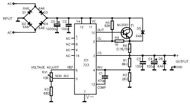
This LM723 variable power supply circuit design is a straightforward variable power supply capable of delivering an output voltage ranging from 8 to 30 volts, with a maximum output current of 3 amperes. The circuit features a low output...
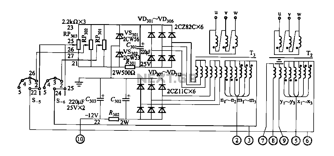
FGDF-3 is a three-phase low-temperature iron plating power supply circuit, while the KGDF-3 is a single-phase low-temperature iron plating power supply device that encompasses all the characteristics of the power supply unit. This design allows for an even distribution...
The search loop can be constructed in various ways; however, the method presented here should provide a solid foundation. Refer to Fig. 2 as a guide for assembling the loop. The loop should be made from non-metallic and moisture-resistant...
This circuit is housed in a compact enclosure and is positioned within the refrigerator, either near the lamp or at the door opening. When the refrigerator door is closed, the interior remains dark, causing the photoresistor R2 to exhibit...
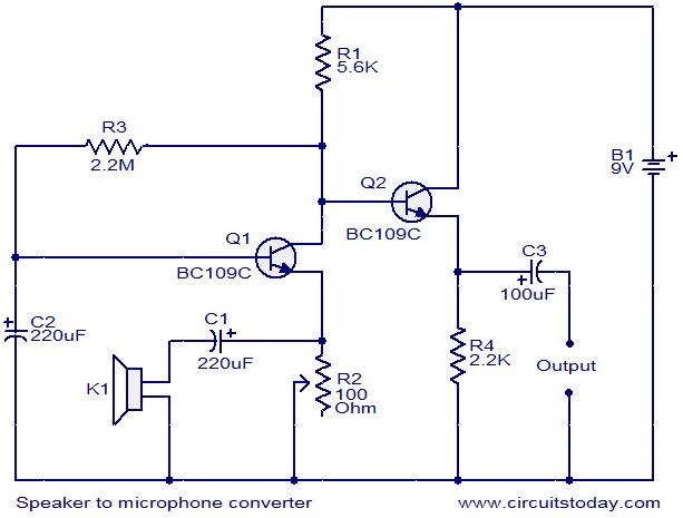
This circuit provides a straightforward method for converting a loudspeaker into a microphone. When sound waves impact the diaphragm of the speaker, fluctuations occur in the coil, generating a small induced voltage that is typically low in magnitude and...