
Speaker to microphone converter circuit

This circuit operates on the principle of electromagnetic induction, where sound waves cause mechanical vibrations in the loudspeaker's diaphragm. These vibrations lead to fluctuations in the magnetic field around the coil, resulting in an induced voltage proportional to the sound pressure level. The low-level signal generated is typically insufficient for direct audio applications, necessitating amplification.
Transistor Q1, configured in common base mode, serves as the primary voltage amplifier. In this configuration, the input signal is applied to the emitter while the output is taken from the collector. This arrangement provides a high input impedance and low output impedance, allowing for effective voltage gain. The gain factor can be adjusted by varying the biasing conditions, which can be fine-tuned using the preset resistor R2.
Transistor Q2, operating as an emitter follower, is crucial for providing current gain without significant voltage gain. This configuration ensures that the output signal can drive subsequent stages or loads without distortion, preserving the integrity of the audio signal. The emitter follower's high input impedance and low output impedance characteristics make it ideal for interfacing with other audio equipment.
Overall, while this circuit does not replicate the fidelity of a conventional microphone, it offers a practical solution for simple audio applications where moderate quality is acceptable. The ability to adjust R2 allows for optimization of the sound quality based on the specific characteristics of the loudspeaker used, facilitating a customizable audio experience.This circuit is a simple approach for converting a loud speaker into a microphone. When the sound waves fall on the diaphragm of a speaker, there will be fluctuations in the coil and there will be a small proportional induced voltage. Usually this induced voltage is very low in magnitude and useless. Here in the circuit the low voltage is amplifie d using transistors to produce a reasonable output. The transistor Q1 is wired in common base mode and produces the required voltage gain. The transistor Q2 is wired as an emitter follower to produce enough current gain. The voice quality of this circuit will not be as much as a conventional microphone but quite reasonable quality can be obtained. To set up the circuit, keep the preset R2 at around 10 Ohms and connect the battery. Now adjust R2 to obtain the optimum sound quality. 🔗 External reference
Related Circuits
To complement the 60 Watt MOSFET audio amplifier, a high-quality preamplifier design was necessary. A discrete component topology, utilizing +24V and -24V supply rails, was selected, minimizing the transistor count while ensuring low noise, very low distortion, and a...
This UHF wideband amplifier (Ultra High Frequency amplifier) provides a total gain of 10 to 15 dB in the frequency range of 400 to 850 MHz, making it suitable for areas with weak TV signals. For optimal performance, the...
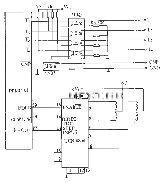
The PPMC external UChl 5804 demonstrates a four-phase stepping motor drive integrated circuit (IC) that is depicted in a downward motion. It utilizes the P-OUT, counterclockwise (ccw) / clockwise (cw), and HOLD outputs. The UCN5804 pins 9 and 10...

This circuit is designed as a low dropout charger using a MOSFET as the pass element; however, it does not incorporate current limiting. The circuit diagram illustrates a straightforward design. It utilizes Q3 and a Schottky diode to isolate...
This circuit is designed to control the mains pulse. The pulser's purpose is to switch the mains voltage on and off at intervals ranging from just under one second to a maximum of ten minutes. This functionality is beneficial...
The circuit output voltage can be continuously adjusted from zero to its maximum value. The baseline is established by a constant current sourced from the auxiliary power supply circuit. The reference current of 500 microamperes can be fine-tuned to...