
BASIC CIRCUITRY of Metal Detection

The construction of a search loop for metal detection involves several critical design considerations. The choice of materials is paramount; non-metallic and moisture-resistant components help ensure the loop's durability and performance. The geometry of the loop, including its width and the number of turns of wire, directly influences its inductance and resonant frequency. The oscillator circuit must be designed for stability, with careful attention to lead lengths and component mounting to minimize parasitic capacitance and inductance.
When tuning the oscillator, it is essential to understand the relationship between capacitance, inductance, and frequency. The adjustments made to the variable capacitors (C5 and C6) allow for fine-tuning the oscillator to match the frequency of nearby radio stations, thus enabling effective detection of metal objects through heterodyning. The use of a frequency counter or shortwave receiver provides a means to accurately assess the oscillator's output frequency, facilitating precise tuning.
The incorporation of a Faraday shield serves to reduce the impact of ground capacitance on the oscillator's frequency, thereby improving detection reliability. By creating a controlled environment around the loop, the shield minimizes unwanted frequency shifts that can occur due to variations in ground conditions.
The ergonomic design of the search loop, including a handle for ease of use, enhances the user experience during operation. The overall assembly must be robust yet lightweight to allow for extended use without fatigue. This careful consideration of both electronic and mechanical aspects culminates in a functional and effective metal detection system.The search loop may be constructed in several different ways; however, the method offered here should get you headed in the right direction. Refer to Fig. 2 as a guide for constructing the loop. The loop form should be constructed from non-metallic and non-moisture-absorbent material. A sealed wood form will do, and it can be either solid or hoop- like. The form should be % to 1 inch wide to allow room for the coil windings. Close wind six turns of #20 enameled or insulated wire on the form. Wrap the windings with at least two layers of good quality plastic electrical tape. Put the loop aside and construct the oscillator circuit on a piece of multipurpose PC board with pre-drilled holes. Stability is one of the most important considerations in building any stable oscillator circuit, so keep all component leads short and solidly mounted.
The two variable capacitors should be mounted in a manner that allows tuning from outside the enclosure. In order to achieve the best results, the circuit should be housed in a metal cabinet to which the circuit ground is connected.
Temporarily connect the loop to the circuitry with about 30 inches of shielded microphone cable or 2-conductor intercom wire. Any wire gauge from #18 to #24 will do. Actually two insulated wires may be twisted together by hand and used. Place the loop away from any metal object and apply power to the circuit. Locate a transistor radio near by and tune in a station somewhere near the middle of the dial. Adjust both C5 and C6 to a frequency that will heterodyne with the broadcast station. If nothing happens, it is most likely that the oscillator is not operating near the desired frequency.
Now, how do we determine if the oscillator`s frequency is too low or too high Naturally, a frequency counter would be the easiest way to determine the oscillator`s frequency. If one is not available, what then A shortwave receiver that runes both below and above the standard AM broadcast band can be used to ferret out the oscillator`s frequency.
Once the oscillator`s frequency is determined, adjustments can be made to move the frequency into the broadcast band. Reducing the total capacitance of the oscillator`s tuned circuit or lowering the inductance of the loop will raise the frequency.
Lowering the frequency is accomplished by increasing the capacitance of the tuned circuit or by increasing the inductance of the loop. Removing or adding a turn to the loop is a good method to use if the oscillator is way off frequency.
The search loop normally scans the ground in a parallel manner in search of metal objects. The loop`s parallel position to the ground forms a capacitance to ground, which shifts the oscillator`s frequency. As the loop moves up and down above the ground, the oscillator`s frequency shifts in a like manner. Adding a Faraday shield to the loop will help in reducing the ground-effect frequency-shift problem. The Faraday shield is a metal shroud that is formed around the loop with an insulating gap in the middle.
A shield can be formed out of aluminum foil by cutting a length that`s 3 inches wide and long enough to go almost completely around the edge of the loop while leaving a gap of 1 to 2 inches in the middle, see Fig. 3. Once the aluminum foil is formed, add a 4-inch length bare wire under the foil at one end and glue the shield in place.
Place the loop on a flat surface and place a solid object on top to secure the foil to the loop form. After the glue dries, connect the other end of the bare wire to the loop`s ground-end connection. An old broom handle or dowel rod is attached to the middle of the loop and serves as the handle and support for the loop and detector circuit.
See Fig. 4. The AM radio may be attached to the handle as well or carried separately. Position the loop over the area to be searched and tune the oscillator to produce an audible beat frequency tone. Maximum sensitivity is achieved wh 🔗 External reference
Related Circuits
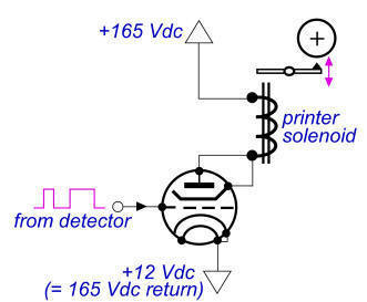
The 900 Hz tone is generated using an LC oscillator. The inductive component, "L," is provided by the inductance of the oscillator's output coupling transformer T1. This configuration is a variation of one of the two standard Hartley oscillator...
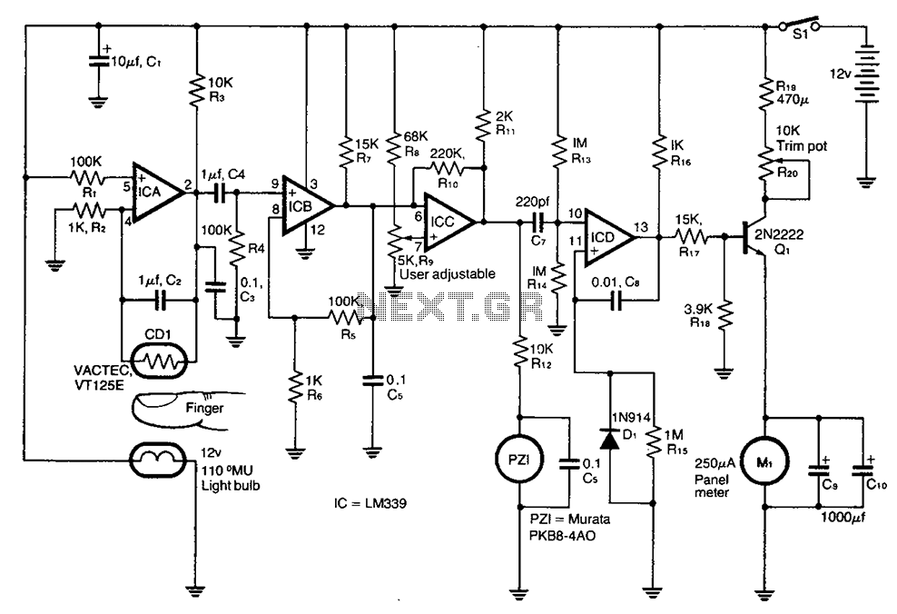
A cadmium sulfide photoresistor (CD1) fingertip can be detected through the filter. CD1 forms part of the sense amplifier feedback network. A section of the sense amplifier (ICA) produces weak signals that may be further amplified by ICB. These...
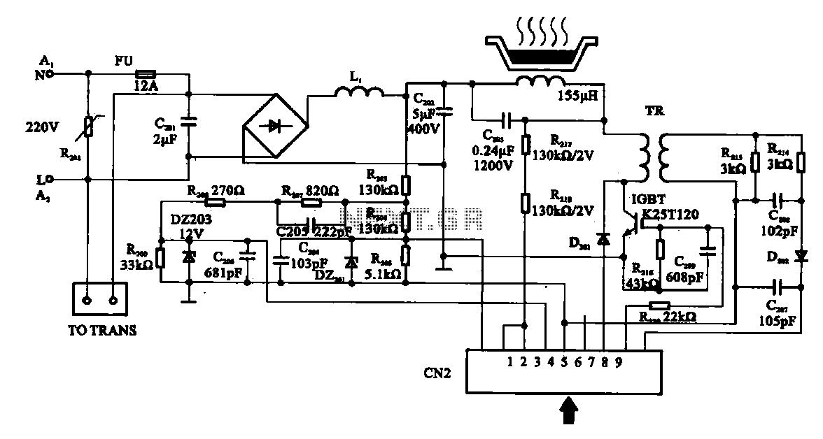
Cooker detection control circuit. The control circuit is designed for testing cookers. The inductance coil disc lesion typically measures around 150 µH. The stove plate coil and capacitor resonate with device C203. When resonating, the voltage generated across C203...
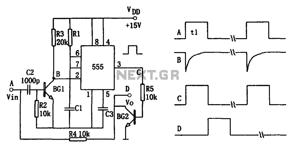
The pulse-width detection circuit is illustrated in the figure and consists of a differential circuit (R2, C2), an amplifier (BG1), a single stabilizing circuit (555, R1, C1), and various other components. The pulse signal Vin (depicted as waveform A)...
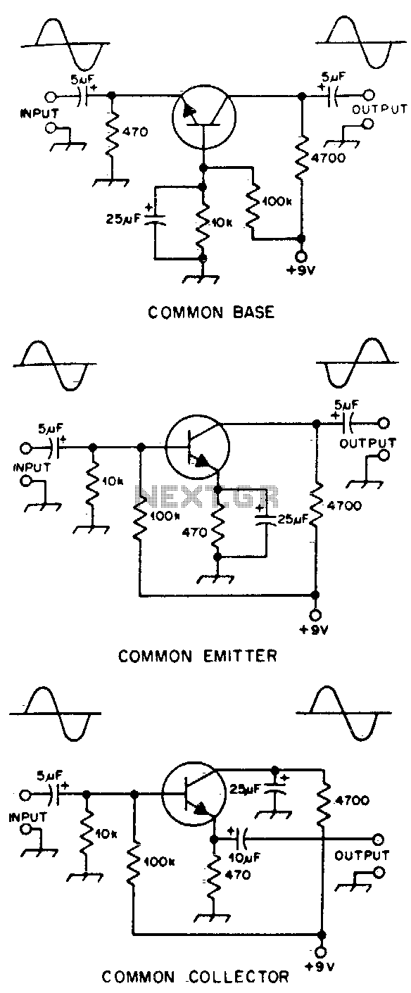
Typical component values are provided for use at audio frequencies, where these circuits are most commonly utilized. The input and output phase relationships are illustrated. The circuit design focuses on audio frequency applications, emphasizing the selection of component values that...
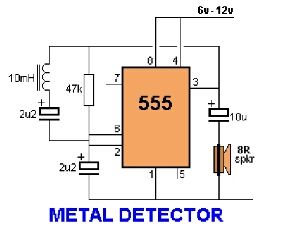
Assemble the circuit on a perfboard or PCB, excluding the inductor. Attach two long wires in place of the inductor. Use a long rod and position the inductor. The circuit assembly begins with the preparation of a perfboard or printed circuit...