
Add a sensor to a board and measure something with it


The proposed device serves as a critical safety mechanism for maritime operations, particularly in conditions that may lead to instability and potential capsizing. The accelerometer measures the tilt of the vessel, allowing for real-time monitoring of its heel angle. By integrating a microcontroller, the system can process the accelerometer data and correlate it with predefined squall curve parameters to determine the risk level associated with wind gusts.
The incorporation of three-axis measurement capabilities enables a comprehensive analysis of the vessel's orientation, which is essential for accurate risk assessment. Each LED output corresponds to specific gust thresholds, providing immediate visual feedback to the crew regarding the severity of wind conditions. The use of low-pass filters is vital in this application, as it helps to eliminate high-frequency noise from the accelerometer readings, ensuring that the measurements reflect the true dynamics of the vessel's movement.
The modular design, with a separate board for the accelerometer and filters, allows for flexibility in testing different accelerometer models and configurations. This adaptability is crucial for optimizing the device's performance based on various vessel types and operational conditions. Future integration of an anemometer input will enhance the device's functionality by allowing it to cross-reference wind speed with the heel angle, further refining the risk assessment process.
Overall, this device aims to enhance maritime safety by providing real-time warnings of conditions that could lead to a knockdown, thereby aiding in the prevention of maritime accidents associated with adverse weather conditions.This weekG•s plan is to build a device that warns of the potential of a knockdown the process by which an over-canvassed ship is lain over on her beam-ends. The potential for sinking at this point is high, so it is an event to be avoided. As the reading of squall curves (from vessel stability booklets) is a skill rarely practiced these days, s
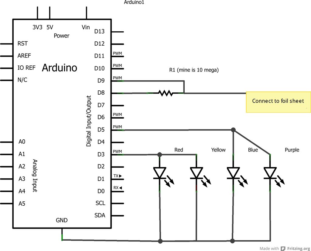
uch a device has merit. A squall curve diagram generally indicates the maximum angle of heel recommended for a given wind velocity, and the potential for gusts. At a basic level, assuming a prevailing wind of 25 knots (beaufort force 6), this device will measure heel (inclination) and indicate the level of gust that would present a knockdown risk based on that angle of heel, by flashing a LED for either 60 knots, 45 knots or 30 knots.
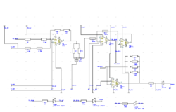
I based the design around an accelerometer, with the plan being to trial more than one. The sort we have in stock is a single axis, but Lindy had an ADXL335, 3-axis (one of the new ones, and it was around this that I designed the circuit. With three axis inputs, and three LED outputs, I needed to use the ATMega88 new for me. I designed the circuit so that the accelerometer resided on a separate board with three passive lo-pass filters that would connect to the main board via a 2x3 pin arrangement.
I set the board up this way so that I could experiment with several accelerometers, hoping to ultimately build my own using a flexure. The ADXL335 has resistors built in resistors so technically I donG•t need the ones in the above diagram, and they are zero ohm.
I included them on the advice of a former technical director at RIM who said she always made provision for them, so she could tweak the filter later if necessary. Alas, I could not get the AVRISP to recognize the board. I troubleshot every connection on the board, and they all seem to work. The easiest component to suspect is the ATMega maybe I cooked it while soldering, or maybe I shorted it out at some stage.
For coming weeks, (once I get this working) IG•d like to add an input from an anemometer (wind indicator) and have the device interpret both inputs against the squall curves. I may combine this with Output devices.
Related Circuits

This is a simple electronic thermometer circuit. It is an inexpensive circuit because the probe or sensor used in this circuit is a 2N2222 silicon transistor. The electronic thermometer circuit utilizes the 2N2222 silicon transistor as a temperature sensor. The...
This project is an Arduino-based light control system that is ideal for beginners. It allows the fading of colors or lights by detecting hand movements nearby. The system transitions from a purple-blue hue to a fiery red-orange. The assembly...
A Fresnel lens is a thin disc made of glass or plastic featuring a series of concentric stepped rings. Each successive step from the central ring has the surface curvature of a much thicker lens. Fresnel lenses are utilized...
It's basically a photovore with a couple tactile sensors. It's rather complex but can give neat behaviors with modifications to the circuit. At this point I don't have any plans to give more information on this circuit so your...
This week involved the completion of several objectives. Initially, software was downloaded to design the schematic for a circuit intended for translation onto a PCB. A significant portion of the week was dedicated to tutorials and familiarization with the...
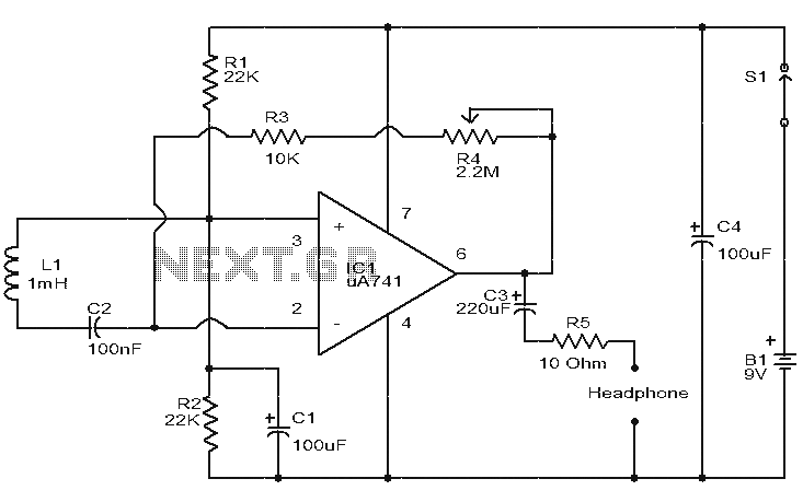
This is a simple circuit designed to detect electromagnetic radiation, including hidden wiring. It utilizes a 1mH inductor to sense the electric field. The induced voltage from the inductor is amplified by an operational amplifier (op-amp). An audio headset...