
Biosensor circuit
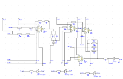
The circuit design process began with the selection of an appropriate software tool that facilitates schematic creation and PCB layout. The chosen software allows for intuitive manipulation of components and wiring, enabling the designer to effectively visualize and implement the circuit's functionality. The design incorporates essential elements such as resistors, capacitors, and operational amplifiers, which are critical for the intended application.
The inclusion of battery switches is a key feature, providing the ability to easily disconnect the power source when the circuit is not in use, thereby extending battery life and enhancing safety. The DIP switch serves as a versatile control mechanism, allowing for the adjustment of resistance values in the circuit. This adaptability is crucial for testing and optimizing circuit performance under various conditions.
Once the schematic was finalized, the design was prepared for manufacturing. The Biomedical Technology Workshop was engaged for the fabrication of a prototype case, which serves not only a protective function but also contributes to the overall design aesthetics. Careful consideration was given to the case design to ensure it is visually appealing while maintaining functionality. This prototype will facilitate further testing and validation of the circuit's performance before proceeding to the PCB stage, thus ensuring that all design objectives are met effectively.This week was spent completing a number of different objectives. Firstly, the software was downloaded to design the schematic for the circuit to be translated onto a PCB. Much of the week was spent doing tutorials and learning the user interface to make a nice circuit. Also, the circuit, complete with switches for the batteries as well as a DIP switch to control resistance, was given to the Biomedical Technology Workshop for manufacturing into a case. This will serve as the first prototype (not the PCB), and steps were taken in order to ensure it was pleasing to the eyes.
🔗 External reference
Related Circuits

Useful for A/B control, the IR receiver shown controls a relay from an infrared beam that has a pulsed tone-modulated signal. Q1 is the photo receptor feeding op amp IC1, tone decoder IC2, and flip-flop IC3. IC5 turns off...
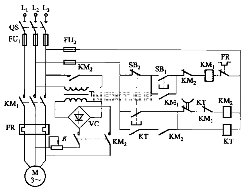
The circuit depicted in Figure 3-135 employs a time relay (KT) to determine the braking time. The circuit utilizes a time relay, which is a crucial component for controlling the duration of the braking process. The time relay KT is...

An electric power limiter circuit restricts the user load, ensuring that household appliances operate within a specified normal current range. When the load exceeds a predetermined threshold, the power supply is disconnected. This circuit utilizes the high-power integrated TWH8778...
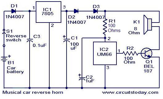
This circuit is designed to produce a musical horn whenever a car is in reverse gear. It utilizes two integrated circuits (ICs) for its operation: a voltage regulator (7805, referred to as IC1) and a musical tone generator (UM66,...
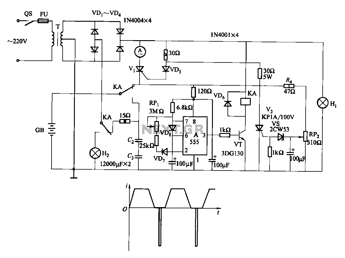
Fast and efficient charging is significantly higher than conventional charging, achieving a current charge that is ten to several times greater. When the battery voltage reaches a predetermined level (known as the polarization point), polarization within the cell becomes...
Note: Do not build or use this if you do not have any knowledge in electrical or electronics. This project is not safe for beginners, and the voltage involved is dangerous and can cause electrocution. Do not exceed the...
Warning: include(partials/cookie-banner.php): Failed to open stream: Permission denied in /var/www/html/nextgr/view-circuit.php on line 713
Warning: include(): Failed opening 'partials/cookie-banner.php' for inclusion (include_path='.:/usr/share/php') in /var/www/html/nextgr/view-circuit.php on line 713