
EMF sensor circuit diagram
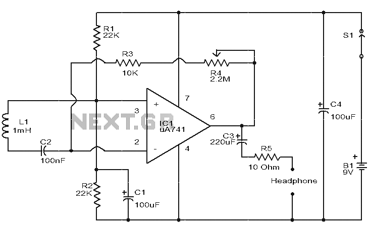
This electromagnetic radiation detection circuit operates by utilizing the principles of inductance and amplification. The core component, the 1mH inductor, acts as a sensor that detects variations in the electric field caused by nearby electrical devices or wiring. When the inductor is exposed to an electric field, it induces a voltage proportional to the strength of that field. This induced voltage is typically very small, necessitating amplification for practical audio output.
The operational amplifier serves as the main amplification stage, where the induced voltage is increased to a level suitable for audio output. The gain of this amplifier can be finely adjusted using the potentiometer R4, allowing the user to tailor the sensitivity of the circuit based on the surrounding electromagnetic environment. This feature is particularly useful when trying to detect weak signals or when the circuit is used in environments with varying levels of electromagnetic noise.
The audio output is connected to a headset, enabling real-time monitoring of the detected signals. The circuit is capable of picking up low-frequency hums, such as the 50 Hz from power transformers, which can be heard as a distinct sound through the headset. Additionally, when the sensor is placed close to telephone lines, it can pick up and amplify the audio signals from conversations, demonstrating its potential for both educational and practical applications.
Powering the circuit with a 9V PP3 battery ensures portability and ease of use. The inclusion of a sliding switch (S1) allows the user to easily turn the device on and off, conserving battery life when the circuit is not in use. It is essential to ensure that the integrated circuit (IC1) is securely mounted in its holder for reliable operation. Furthermore, all electrolytic capacitors in the circuit should be rated for at least 15V to prevent failure under operational conditions. Proper assembly and adherence to these guidelines will result in a functional and effective electromagnetic radiation detection circuit.This is a very simple circuit that can detect electromagnetic radiation. The circuit can even detect hidden wrings. A 1mH inductor is used to sense the electric field. Induces a small electric field sensor inductance voltage, this induced voltage amplification opamp.The headset connected to the output of the operational amplifier audio instruction field. For example, the electric field around the power transformer 50 Hz hum can be heard. R4 pot can be used to adjust the gain of the amplifier. By keeping inductance sensor near a telephone line, you can even hear the telephone conversation. Circuit diagram and parts list Precautions In general PCB assembly circuit. The circuit can be powered from a 9V PP3 battery. This is better for the radial inductor L1. R4 pot can be used to adjust the gain. A switch S1 to ON / OFF switch sliding. You must install IC1 holders. All electrolytic capacitors must be rated for at least 15V.
Related Circuits
This is a non-contact power regulator circuit designed for a light load. By adjusting a 150kΩ potentiometer, phase shift can be achieved, and a trigger voltage is applied to the gate of a bidirectional thyristor through a bidirectional trigger...
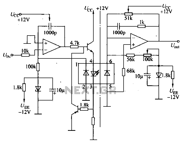
A universal optocoupler is utilized in electrocardiographs, as illustrated in Figure 5-29. Pin connections must be made carefully: the positive terminal should be connected to pin O, while the negative terminal should connect to the other pin. The control...

AN79 Linear Technology AN79 modifies methods presented in AN74, allowing for the verification of 30 nanosecond amplifier settling times with 0.1% resolution. The sampling-based technique used is detailed, and results are presented. Appendices cover oscilloscope overdrive issues, the construction...

Below is a circuit of power amplifiers with a power output of 450 watts in mono mode. These amplifiers are frequently utilized in high-power applications, suitable for events, and designed for enclosed spaces. This amplifier is appropriate for woofers...

This page presents a circuit featuring twenty open collector outputs that activate sequentially in a continuous, unidirectional loop. The circuit utilizes the 74LSxx family of TTL integrated logic devices. It is designed to drive light-emitting diodes or low current,...
The bicore is the basis of advanced BEAM. Most intermediate to advanced BEAM robots are built off of the bicore. Uses go all the way from photovores to servo motor drivers to walkers. What it is is basically just...