
Adjustable 1-10 Minute Timer Project
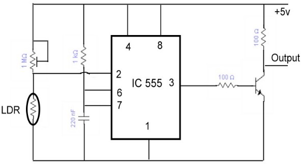
This timing circuit utilizes a straightforward design to provide a visual and auditory indication of elapsed time. The core component is a 220 µF electrolytic capacitor, which, when charged, controls the timing interval. The variable resistor (potentiometer) allows for user-defined adjustments to the timing, offering flexibility in applications where precise timing is necessary.
Upon activation, the circuit begins charging the capacitor through the variable resistor. The green LED serves as an indicator that the timing process is active. The timing mechanism relies on the RC (resistor-capacitor) time constant, which is calculated using the formula τ = R × C, where τ is the time constant in seconds, R is the resistance in ohms, and C is the capacitance in farads.
When the capacitor reaches a certain charge level corresponding to the set time, it triggers a transition in the circuit. This transition is typically managed by a comparator or a microcontroller that detects when the voltage across the capacitor reaches a threshold. At this point, the green LED is turned off, and the red LED is activated to signal the end of the timing period. Simultaneously, the bleeper is engaged to provide an audible alert.
The design should account for the leakage current of the electrolytic capacitor, which can affect timing accuracy. To mitigate this, it is advisable to use high-quality capacitors with low leakage rates. The variability in capacitance values also suggests that users should calibrate the timing circuit after assembly to ensure the desired time intervals are achieved.
In summary, this timing circuit is a versatile tool for applications requiring precise timing with visual and auditory feedback, making it suitable for various electronic projects and experiments.The circuit starts timing when switched on. The green LED lights to show that timing is in progress. When the time period is over the green LED turns off, the red LED turns on and the bleeper sounds. The time period is set by adjusting the variable resistor. It can be adjusted from 1 to 10 minutes (approximately) with the parts shown in the diagra m. You can mark the times on a scale drawn on the box. Please note that the range of time periods is only approximate. With perfect components the maximum time period should be 4 ½ minutes, but this is typically extended to about 10 minutes because the 220 µF timing capacitor slowly leaks charge. This is a problem with all electrolytic capacitors, but some leak more than others. In addition the actual value of electrolytic capacitors can vary by as much as ±30% of their rated value.
🔗 External reference
Related Circuits
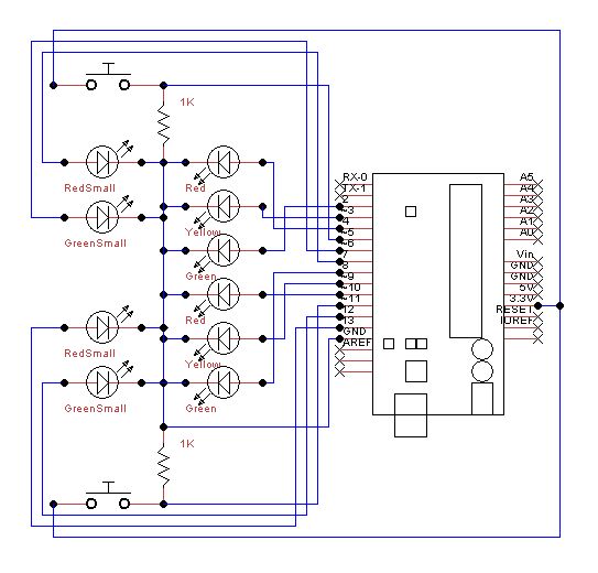
Set up the lights on the breadboard to resemble a traffic light configuration. The red LED should be positioned at the top, followed by the yellow LED, and then the green LED. The small red and green LEDs will...
The SE555/NE555 timer was first introduced by Signetics Corporation around 1971. The pin connections and their functions are as follows: Pin 1 (Ground) is the most-negative supply potential and is typically connected to circuit common when powered by positive...

This circuit operates as an astable multivibrator. With switch S9, an octave can be chosen. The tones are set by P1 to P8. Pressing S1 to S8 displays the corresponding note; pressing two buttons at the same time gives...
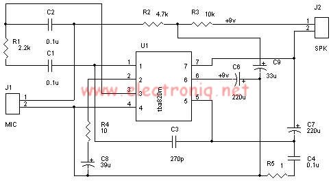
A very simple audio amplifier circuit can be designed using the TBA820M audio amplifier integrated circuit with just a few electronic components. This audio amplifier project features a high gain that allows for the detection of sounds underwater. The...
This project was designed to introduce a friend to microcontrollers and circuits using various functionalities and spare parts. A PS2 numpad was utilized as the key entry mechanism, which was found at a thrift store and included the necessary...
An 8051 microcontroller-based electronics project that demonstrates the creation of an automated car parking system. This project features a multi-floor parking structure with a lift that transports cars to designated parking areas based on the occupancy status of the...