
Traffic Lights Beginner Arduino Project
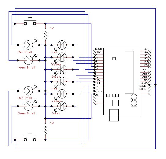
To create a functional traffic light circuit on a breadboard, the following components are required: three LEDs (red, yellow, green), two additional smaller LEDs (red and green for pedestrian signals), buttons, a 1 kΩ resistor, and jumper wires.
The main traffic light configuration consists of the three larger LEDs arranged vertically. The red LED is positioned at the topmost location on the breadboard, followed by the yellow LED in the middle, and the green LED at the bottom. Each LED should be connected to a suitable current-limiting resistor (typically around 220Ω to 330Ω) to prevent excessive current from damaging the LEDs. The anodes (longer leads) of the LEDs should be connected to the positive voltage supply, while the cathodes (shorter leads) are connected to the ground through the resistors.
The pedestrian crossing signals are represented by the smaller red and green LEDs. The red pedestrian signal should be placed directly above the green pedestrian signal. Similar to the main traffic lights, these LEDs also require current-limiting resistors connected in series.
The buttons serve as manual control mechanisms for the traffic lights and pedestrian signals. Each button should be connected with at least two pin holes of space on either side to accommodate the necessary wiring and resistors. The configuration involves connecting one terminal of each button to the positive voltage supply and the other terminal to the respective LED circuit. The 1 kΩ resistor should be placed between the button terminal connected to the LED circuit and the negative rail on the breadboard, ensuring that pressing the button completes the circuit and activates the corresponding LED.
Connections should be made using jumper wires to establish links between the LEDs, buttons, and the power supply. It is essential to verify the polarity of the LEDs and ensure that all connections are secure to facilitate proper operation of the traffic light system. This setup will allow for the demonstration of traffic light sequences and pedestrian signal activation in a compact and visually intuitive manner.Setup the lights on the breadboard like a traffic light. Red on top, then yellow, and then green. The small red and green are the pedestrian crossing signals. Again red on top and green just below. Put the buttons in so you have at least 2 pin holes space to add the wires and resistors. Place the 1kohm resistor between one side of the button and t he negative run on the breadboard. 🔗 External reference
Related Circuits
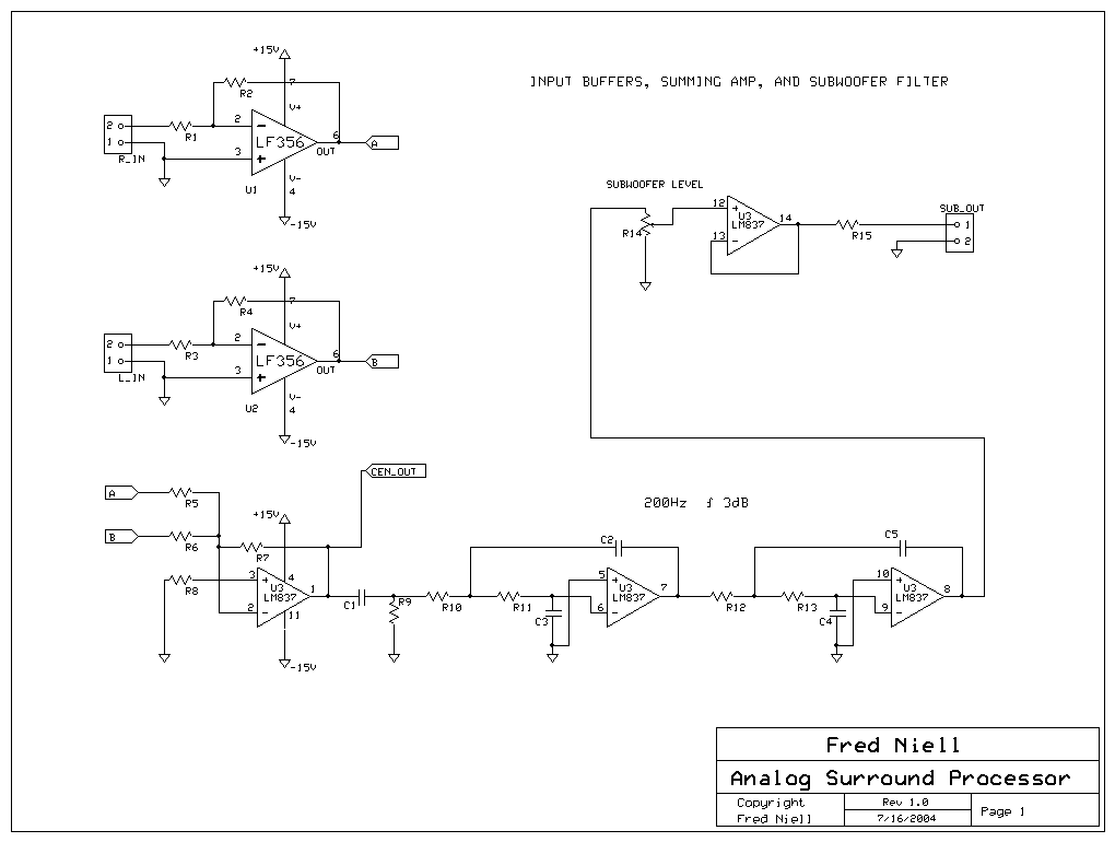
The overall block diagram of the system shows that audio input enters from the left and undergoes various processing steps including summation, differencing, multiplication, delay, and filtering. The output consists of five discrete audio channels along with one low-frequency...
Model railroad turnouts, often referred to as switches, can be controlled in various ways. The simplest method is manual control, operated by hand. Remote activation is typically achieved through pneumatic (air) or electrical means. The project discussed in these...

The primary component utilized is the ACS712 sensor from Allegro MicroSystems, designed for measuring current. It offers cost-effective and accurate solutions for AC or DC current sensing in industrial, commercial, and communication systems. A precise, low-offset, linear Hall sensor...

This is my first project with an SMD circuit. I previously avoided SMD components due to confusion caused by their small size. The circuit for the current SMD project involves headphones. The project focuses on designing a compact headphone amplifier...
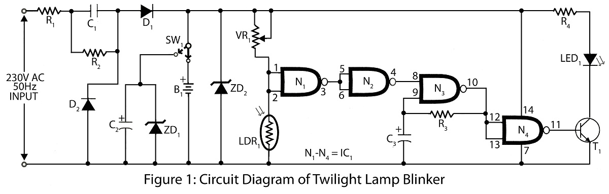
Twilight Lamp Blinker circuit can be constructed using a Light Dependent Resistor (LDR) and a single integrated circuit (IC). The circuit diagram includes a parts list for various projects utilizing the LDR and additional components. The Twilight Lamp Blinker circuit operates...
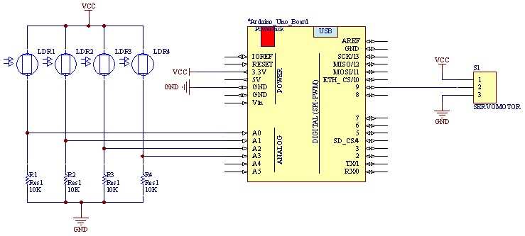
The movement of the servo is determined by the output values of the photoresistors. The impedance of these sensors changes with the amount of light incident upon them. The servo's position shifts towards the sensor that detects less light....