
adjustable current limiter circuit

The circuit operation begins with resistor R1, which senses the current. When the potentiometer R2 is set to its minimum resistance (with the center tap connected to R1), if the load current reaches 1.2 A, the voltage across R1 will reach 0.6 V, causing transistor Q2 to conduct. This action shorts the base voltage of transistor Q4 to ground, reducing the base current and consequently lowering the output voltage sensed by the load, thereby preventing further current flow. For lower current limiting thresholds, R1 can be changed to 1 Ω, providing an adjustment range of approximately 0.7 A to 4.2 A.
Due to the power dissipation capabilities of the 2N3055 transistor, in the worst-case scenario where the load is shorted to ground (zero resistance), the circuit can handle a maximum source voltage of 14 V while limiting the current to 8.4 A. Conversely, limiting the current to 4.2 A allows for a maximum source voltage of 27 V. The circuit can withstand a maximum voltage of 60 V, but under extreme conditions (load shorted to ground), the current limit should be set to a safe maximum of 1.9 A. It is essential for transistor Q1 to be equipped with an adequate heat sink.
The circuit utilizes a combination of resistors, potentiometers, and transistors to achieve its current limiting functionality. The configuration allows for flexibility in current settings and ensures that the load does not exceed the specified limits, thereby protecting both the power supply and the connected devices. The careful selection of components and their arrangement in the circuit is crucial for achieving reliable performance and maintaining safe operating conditions.This circuit is design for provide automatic current limiting up to 8. 4A. Unlike current limiter that uses only a resistor, this current limiting circuit doesn`t drop the voltage, or at least keep the voltage drop at minimum, until a certain current amount is exceeded. This current amount limit is adjustable from 1. 4 A to 8. 4A by a potentiometer. You can modify the component value to give different current limiting range. This is the simple figure of the circuit. How is the circuit work First, the resistor R1 is there to sense the current. At R2 potentiometer at minimum resistance (the center tap connected to R1), if the current drawn by the load reach 1. 2A then the voltage across R1 reach 0. 6V and Q2 begin conducting, thus shorting the base voltage of Q4 to ground. This shorting action to reduces the base current and therefore reduce the output voltage sensed by the load, and prevent the current to flow further.
If you need the current limiter to limit at lower threshold range, you can change the R1 to 1R and you`ll get about 0. 7A to 4. 2A adjustment range. Because of the power dissipation capability of 2N3055 transistor, at the worst case that the load is shorted to ground (zero resistance), when you limit the current to 8.
4 A then the circuit can handle maximum source voltage of 14V, while limiting the current at 4. 2A can handle up to 27V source voltage. The maximum voltage that can be handled the circuit is 60 volt, but you can only safely set the current limit at 1. 9A in the extreme condition, when the load is shorted to ground. The Q1 transistor must use sufficient heat sink. [Schematic project source: Hasan Murod]. 🔗 External reference
Related Circuits
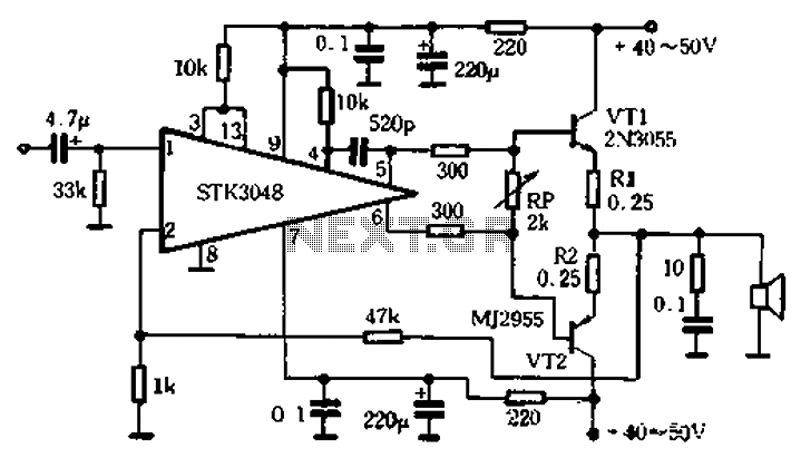
The circuit utilizes the high-power complementary tube STK3048, which operates at high voltage and offers a wide dynamic range. It features an accurate differential input pair, with a common emitter configuration and output terminals connected to a collector constant...
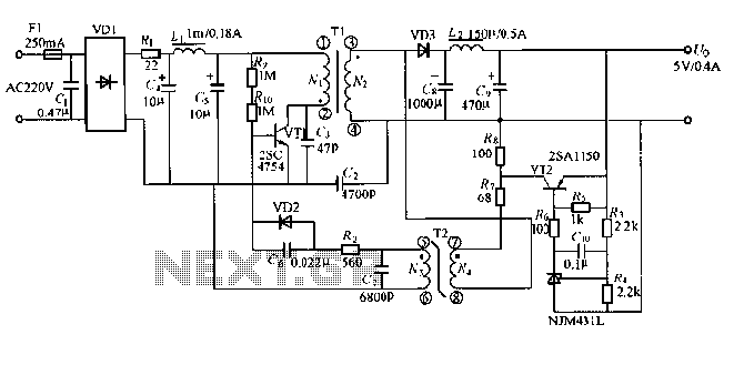
The output displays a 5V / 0.4A low-power switching power supply circuit, which can be utilized to create a transformer saturation soft-switching circuit. This low-power switching power supply circuit is designed to provide a stable 5V output at a current...
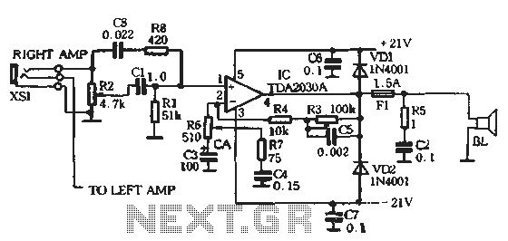
The circuit comprises two main components: the Lisheng power amplifier and the rectifier filter section. The stereo audio power amplifier circuit diagram, depicted in Figure 5-85, illustrates only one channel, with the other channel being identical. The audio signal...
This project utilizes an LM338 adjustable three-terminal regulator to deliver a current of up to 5A with a variable output voltage ranging from 2V to 25V DC. It is particularly useful for powering various electronic circuits during the assembly...
The circuit devised by Phil Allison still has some input voltage limitations, since it is based on a FET. Junction FET VCAs also create considerable distortion, with the worst of it appearing when the signal is attenuated by 6dB....
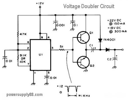
This circuit diagram represents a DC voltage doubler and DC converter. It is designed to convert a 12V DC power supply into outputs of 24V DC and 18V DC. Nearly any PNP or NPN power transistors can be utilized...