
2v to 25v 5a lm338 power supply circuit
The circuit design begins with the AC mains input, which is connected to a fuse (F1) that serves as a protective element, ensuring that excessive current does not damage the circuit. The fuse is rated for 8A, providing a safeguard against overcurrent conditions. Following the fuse, a varistor (V1) is integrated into the circuit to absorb voltage spikes, protecting sensitive components from transient surges.
The transformer (T1) plays a crucial role by stepping down the high voltage AC mains to a lower voltage of 24V AC. This reduction in voltage is necessary for safe operation of the subsequent components. The output from the transformer is directed to a bridge rectifier composed of four diodes (D1, D2, D3, D4). This configuration converts the AC voltage to pulsating DC voltage, which is essential for the operation of the LM338 regulator.
To stabilize the rectified DC voltage and reduce ripple, an electrolytic capacitor (E1) is connected in parallel with the output of the rectifier. This capacitor charges during the peaks of the rectified voltage and discharges during the troughs, effectively smoothing out the voltage fluctuations.
The LM338 adjustable voltage regulator is then connected to provide a stable output voltage adjustable between 2V and 25V. This regulator is capable of supplying up to 5A, making it suitable for various applications requiring different voltage levels. The output voltage can be set using external resistors connected to the adjust pin of the LM338, allowing for precise control over the output voltage.
Overall, this power supply design is versatile and can be adapted to different input voltage requirements by selecting appropriate components, ensuring reliability and performance in powering electronic devices.This project uses a LM338 adjustable 3 terminal regulator to supply a current of up to 5A over a variable output voltage of 2V to 25V DC. It will come in handy to power up many electronic circuits when you are assembling or building any electronic devices.
The schematic and parts list are designed for a power supply input of 240VAC. Change the rat ings of the components if 110VAC power supply input is required. As shown in the figure above, the mains input is applied to the circuit through fuse F1. The fuse will blow if a current greater than 8A is applied to the system. Varistor V1 is used to clamp down any surge of voltage from the mains to protect the components from breakdown. Transformer T1 is used to step down the incoming voltage to 24V AC where it is rectified by the four diodes D1, D2, D3 and D4.
Electrolytic capacitor E1 is used to smoothen the ripple of the rectified DC voltage. 🔗 External reference
Related Circuits
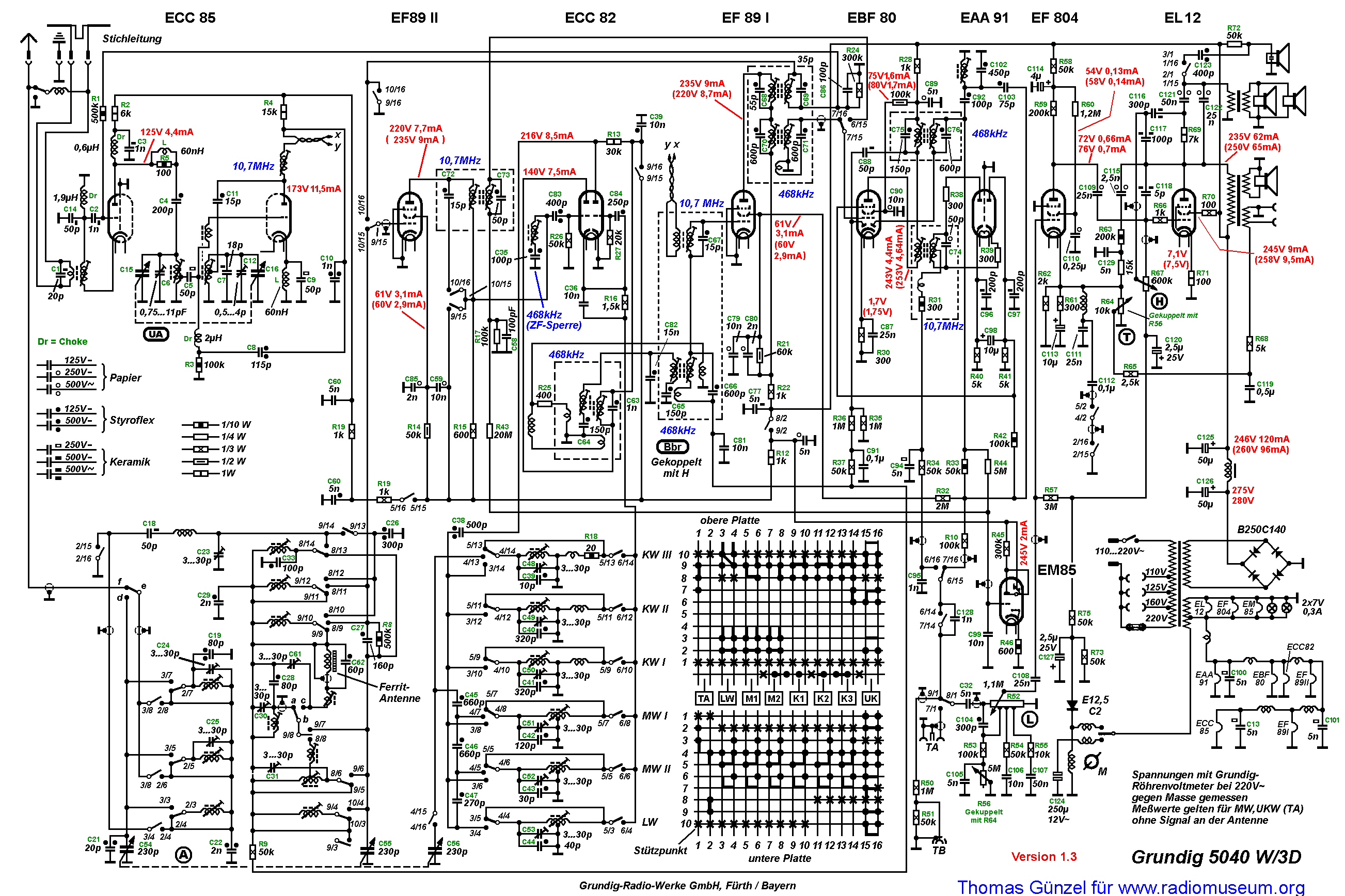
The primary winding of the first IF transformer lacks a capacitor, indicating that it functions as a single tuned circuit with the primary coil serving solely as an inductive coupling. The routing of the twisted pair cannot be replicated...
This circuit utilizes a single integrated circuit (IC) along with a minimal number of external components to display audio levels using ten LEDs. The input voltage can range from 12V to 20V, with a recommended operating voltage of 12V....
The distortion produced by a typical solid-state Class-B power amplifier consists of eight mechanisms, all of which may coexist and whose distortion products overlap to create a complex result. Methods for isolating each mechanism for study and minimizing its...

This circuit includes an amplifier designed to deliver +10 dBm to an SBL series (Mini-Circuits) or a similar type of doubly-balanced mixer assembly. The circuit parameters are specified for 80 to 90 MHz crystals, although the values of the...
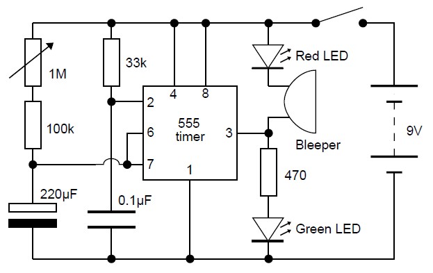
This adjustable analog timer circuit begins timing when it is activated. A green LED illuminates to indicate that the timing is in progress. Upon completion of the set time period, the green LED turns off, a red LED activates,...
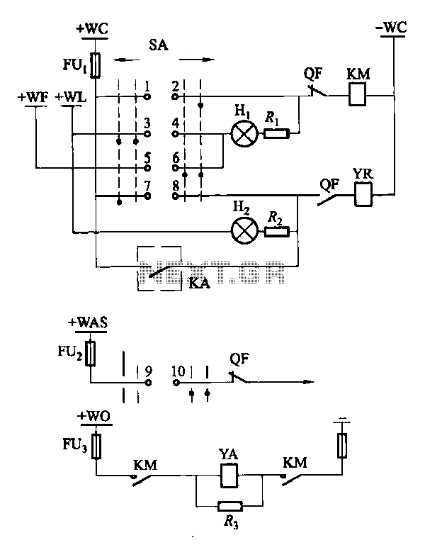
Factories and enterprises operating at voltages of 10 kV and below commonly utilize the CD10 (formerly CD2) type electromagnetic actuator as a circuit breaker. This mechanism features a mechanical anti-jump device. The control signal circuit for the CD10 actuator...
Warning: include(partials/cookie-banner.php): Failed to open stream: Permission denied in /var/www/html/nextgr/view-circuit.php on line 713
Warning: include(): Failed opening 'partials/cookie-banner.php' for inclusion (include_path='.:/usr/share/php') in /var/www/html/nextgr/view-circuit.php on line 713