
Adjustable Current Regulator Circuit Using LM117
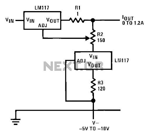
The adjustable regulator circuit featuring the LM117 is designed to provide a stable output voltage that can be varied according to the requirements of the application. The LM117 is a popular choice for voltage regulation due to its ability to deliver a precise output voltage while accommodating a wide range of input voltages.
In this circuit, the LM117 operates in conjunction with a negative supply, which is essential for its proper functioning. The negative supply allows the circuit to maintain a reference point below ground, ensuring that the output voltage can be adjusted effectively. The adjustment is typically achieved through the use of external resistors, which set the desired output voltage level.
The LM117 is configured with two external resistors, R1 and R2, which form a voltage divider network. The output voltage (Vout) can be calculated using the formula:
Vout = Vref * (1 + R2/R1) + Iadj * R2
where Vref is the reference voltage provided by the LM117 (approximately 1.25V), and Iadj is the adjustment pin current, typically negligible in most applications.
The circuit also includes bypass capacitors to stabilize the input and output voltages. A capacitor placed at the input helps filter any high-frequency noise from the supply voltage, while a capacitor at the output improves transient response and stability.
When designing this circuit, it is crucial to ensure that the power ratings of the resistors and capacitors are suitable for the expected load conditions. Additionally, thermal considerations must be taken into account, as the LM117 may require a heat sink for higher output currents to prevent overheating.
Overall, this adjustable regulator circuit with the LM117 provides a versatile solution for applications requiring variable voltage supply while maintaining high efficiency and stability.This circuit shows the adjustable regulator circuit is conjunction with a voltage regulator, but on this circuit using the LM117 regulator of alternative flows in addition to providing a reference, not a diode LM113. Both regulators currently require a negative supply to operate on the ground. Here is a circuit schematic: 🔗 External reference
Related Circuits
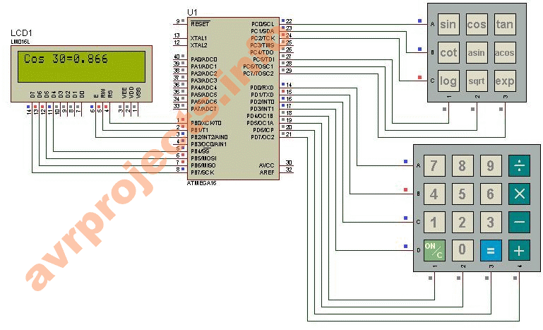
This project provides a straightforward scientific calculator utilizing an AVR microcontroller. It features two keypads as illustrated in the circuit diagram, and the results are displayed accordingly. The scientific calculator circuit based on an AVR microcontroller is designed to perform...
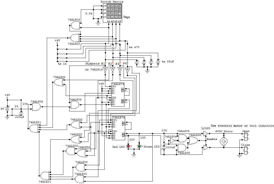
This circuit is an electronic locker controlled by a combination of switches (a code). It features a switch matrix located on the locker door, consisting of a unit of switches arranged in four rows and four columns, totaling eight...
A 1.53 voltage-controlled gain amplifier (VGA) utilizes a FET connected between the two inputs of the operational amplifier (op-amp) as a voltage-controlled resistance. The resistance changes linearly with voltage and varies from several dozen square ohms, exhibiting excellent control...
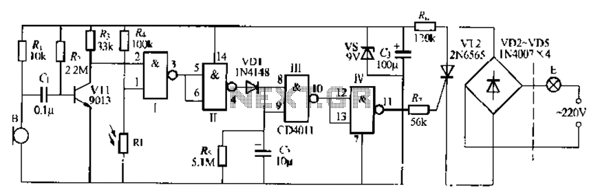
The CDI011 integrated circuit is designed for a sound and light-controlled stair delay switch circuit, which is relatively simple and effective. It utilizes a combination of NAND gates and differential input dynamics. The circuit has two input terminals; when...
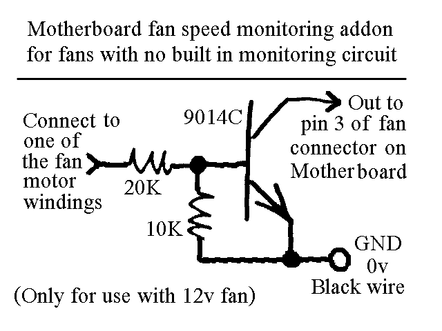
You will find this identical circuit inside most 3 wire computer fans with speed monitoring output to the motherboard. Peel off the sticker from the fan hub in order to access a motor winding pin for connecting up the...
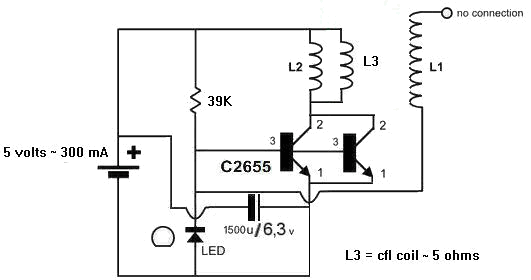
A 1N4148 diode and a 1-megohm resistor are included in the circuit. The inquiry pertains to how to power LED(s) using a 1.5-volt battery. There is also a question regarding the role of an additional coil, L3, and its...
Warning: include(partials/cookie-banner.php): Failed to open stream: Permission denied in /var/www/html/nextgr/view-circuit.php on line 713
Warning: include(): Failed opening 'partials/cookie-banner.php' for inclusion (include_path='.:/usr/share/php') in /var/www/html/nextgr/view-circuit.php on line 713