
Computer fan speed tacho out circuit
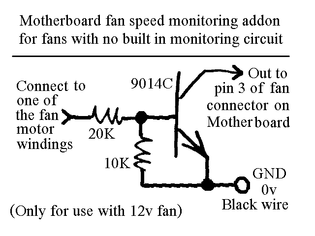
The circuit described is a common configuration found in 3-wire computer fans, which typically consist of three connections: power (VCC), ground (GND), and a tachometer output (TACH). The power and ground wires supply the necessary voltage to operate the fan motor, while the tachometer output provides feedback regarding the fan's rotational speed.
To access the tachometer circuit, it is necessary to peel off a sticker from the fan hub, revealing a pin connected to one of the motor windings. This pin is crucial for measuring the speed of the fan. The fan's internal circuitry generates a pulse signal on the TACH line, which corresponds to the rotation of the fan blades; typically, one pulse is produced for each revolution.
The TACH signal is typically a square wave, where the frequency of the pulses is directly proportional to the fan speed. This signal can be interfaced with a microcontroller or a motherboard fan controller, allowing the system to monitor and adjust the fan speed as needed for thermal management.
In terms of schematic representation, the fan circuit would include a DC motor connected to the power supply, with the TACH output line connected to a microcontroller input pin. Additional components may include a resistor for signal conditioning and capacitors for noise filtering, ensuring a clean and stable output signal for accurate speed monitoring. The design allows for efficient operation and effective thermal control in computer systems, enhancing overall performance and reliability.You will find this identical circuit inside most 3 wire computer fans with speed monitoring output to the motherboard. Peel off the sticker from the fan hub in order to access a motor winding pin for connecting up the tacho circuit.
🔗 External reference
Related Circuits
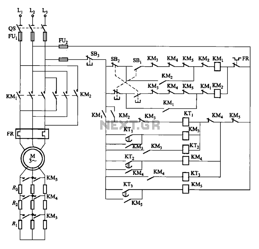
The circuit depicted in Figure 3-162 includes several components: SBi serves as the forward start button, SBz functions as the reverse start button, and SB3 is designated as the stop button. The resistance levels for the start switches are...

This design features a simple yet effective receiver with good sensitivity and selectivity. The circuit utilizes a compact three-transistor regenerative receiver with fixed feedback, primarily based on the BC549 transistor. The tuned circuit is intended for medium wave frequencies...

The circuit is a bell timer. This project utilizes the AT89S52 microcontroller and an I2C EEPROM for storing alarm timings. Additionally, the 7-segment display has been replaced with an LCD display. The DS1307 is employed for real-time clock functionality....

There are many digital thermometers with ±1°C displays, but their accuracy is approximately ±1°C and they cannot be calibrated. A thermometer circuit was created using components available at a local electronics hobby shop, providing an educational experience. For a...
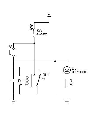
The circuit can also be triggered by logic ICs (TTL/CMOS) using the appropriate interfacing method. Another relay is typically used to serve as the trigger button when interfacing ICs with the latching relay circuit. The described circuit utilizes a latching...

The electronic lantern control circuit enhances an existing battery-powered lantern or flashlight, or can be incorporated into a custom design, by providing high-efficiency dimming and flashing capabilities. This circuit is particularly useful in automotive applications, serving as an effective...