
Voltage controlled gain amplifier circuit diagram
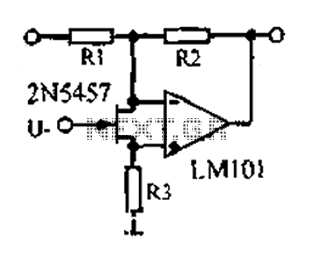
The voltage-controlled gain amplifier operates by modulating the resistance of the FET based on an input voltage signal. This configuration allows for precise control of the gain of the amplifier, making it suitable for applications requiring variable amplification levels. The FET, acting as a voltage-controlled resistor, provides a linear relationship between the control voltage and the resistance, ensuring predictable performance across a range of input conditions.
The circuit typically comprises an op-amp configured in a non-inverting or inverting configuration, depending on the desired gain characteristics. The FET's source and drain terminals are connected to the op-amp inputs, while the gate terminal receives the control voltage. As the control voltage varies, the resistance of the FET alters, thereby changing the gain of the op-amp circuit in a linear fashion.
The performance of the VGA can be further enhanced by selecting appropriate op-amps and FETs that exhibit low distortion and high linearity. Additionally, feedback networks can be incorporated to stabilize the gain and improve bandwidth. Such configurations are widely used in audio processing, instrumentation, and communication systems, where adjustable gain is essential for signal integrity and processing efficiency.
Overall, the design and implementation of a voltage-controlled gain amplifier using a FET as a variable resistor provide an effective means of achieving dynamic control over amplification, making it a valuable component in various electronic applications.1.53 voltage controlled gain amplifier FET connected between the two inputs to the op amp as voltage-controlled resistance, resistance changes linearly with voltage, varies fro m several dozen square, with excellent control characteristics. Each of the resistance depends on the op amp.
Related Circuits
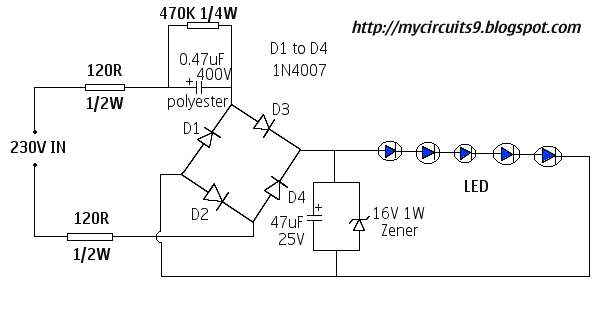
This document presents a 230V LED driver circuit that operates without a transformer. The circuit utilizes five LEDs, although the number can be increased as desired. The absence of transformers significantly reduces both the cost and size of the...
The danger always exists when fuel gases such as propane or natural gas are confined to a small area. The toxic gas alarm utilizes a tin-oxide semiconductor. A coil of thin wire is heated by a 12 V battery...
In this circuit, the 555 timer is utilized in an innovative manner as a voltage-controlled switch. The widely used NE555 can perform effectively in various applications. The 555 timer, a versatile integrated circuit, is commonly employed in timer, delay, pulse...
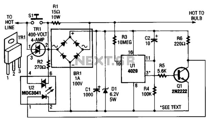
The automatic porch-light control circuit maintains a triac in an active state until a 4020 divider counts a series of 60-Hz power line pulses. This circuit is designed to turn off the light after a specified duration, utilizing pins...
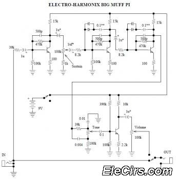
The Electro Harmonix Big Muff Pi circuit would likely benefit from the incorporation of a modern input-jack power connection and a DPDT bypass switch. The specific types of transistors and diodes used in the circuit are not specified. It...
A simple audio amplifier with a 10 Vpp output designed for use with the AD633 ring modulation chip. The datasheet for the chip is available, and the circuit will utilize the XR2206 function generator IC for the modulation input....