
When use Voltage divider in circuit analysis
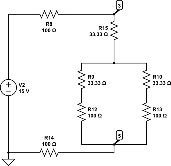
In a circuit where resistors are connected in a Delta configuration, converting to a Wye configuration is often advantageous for simplifying calculations, particularly in series circuits. The conversion from Delta to Wye can be achieved using the following formulas:
\[
R_a = \frac{R_{12} R_{13}}{R_{12} + R_{13} + R_{23}}
\]
\[
R_b = \frac{R_{12} R_{23}}{R_{12} + R_{13} + R_{23}}
\]
\[
R_c = \frac{R_{13} R_{23}}{R_{12} + R_{13} + R_{23}}
\]
Where \( R_a, R_b, \) and \( R_c \) are the resistances in the Wye configuration corresponding to resistors \( R_{12}, R_{13}, \) and \( R_{23} \) in the Delta configuration.
Once the Wye resistances are calculated, the total resistance \( R_{total} \) in the series circuit can be determined by summing the individual resistances:
\[
R_{total} = R_a + R_b + R_c
\]
Using Ohm's Law, the output voltage across resistor \( R_2 \) can be calculated as follows:
\[
V_{out} = V_{in} \times \frac{R_2}{R_{total}}
\]
Given that \( V_{in} = 10V \), substituting the values will yield the desired output voltage. It is crucial to ensure that all resistances are in the same unit (ohms) for accurate calculations. The final output voltage can then be determined by plugging in the calculated resistances into the voltage divider formula.First I convert the Delta R2-R3-R4 to Y (wye), because the Voltage divider should be used in a series circuit so I tried to convert the delta to series, but that just work for find the total Resistance. so in this case $$V_{out} = V_{R_2}$$ I am using $$V_{in} = 10v$$, but I can`t figure out which should be the Total resistance in this case, I mean what is the value of
🔗 External reference
Related Circuits
The impedance of these current generators is essentially infinite for small currents, and they maintain accuracy as long as VIN is significantly greater than VOS and IO is much higher than I bias. The source employs a FET to...
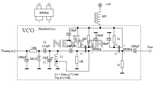
The VCO is based on a Hartley oscillator. The frequency is determined by L1 and capacitor C1. The tuning voltage will change the capacitance in the varactor BB132 which will change the oscillation frequency. The value of capacitor C2...
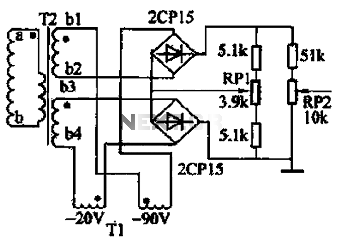
The closed-loop system consists of longitudinal and transverse components. The circuit operates as follows: a control circuit from the stepping motor CNC system issues a command, which the receiver detects. This signal is processed through a phase-sensitive rectifier to...
Electronics Circuits Reference Archive Audio preamplifier circuits. There are thousands of preamplifier circuits. Here are three that are somewhat different and have garnered interest. Intercom preamp: A very convenient way of making an intercom system. Audio preamplifiers are essential components...
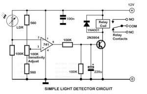
An ambient light sensor circuit is a circuit that utilizes light intensity to perform various applications. An ambient light sensor circuit typically consists of a light-dependent resistor (LDR) or phototransistor that detects the intensity of ambient light. The sensor converts...
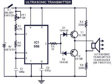
The circuit generates and transmits ultrasonic sound at frequencies between 40 and 50 kHz. It consists of a mini transmitter and a receiver circuit, where the transmitter produces ultrasonic sound, and the receiver detects this sound to activate a...