
IN148 diode temperature measurement circuit

The IN4148 diode temperature circuit is designed to measure temperature variations with high precision and accuracy. The operational amplifier configuration, particularly the use of the LMC660 components, allows for significant amplification of small voltage changes, making it suitable for applications requiring sensitive temperature measurements. The specified temperature range of -25 to 125 °C ensures versatility in various environmental conditions, while the accuracy of 0.5 °C enhances the reliability of readings.
The differential instrumentation amplifier configuration is crucial for rejecting common-mode signals, which could introduce noise and inaccuracies in the temperature readings. By employing three operational amplifiers, the circuit achieves a high input impedance and a low output impedance, facilitating better signal integrity and minimizing the loading effect on the sensor.
The adjustable resistors RP1, RP2, and RP3 provide flexibility in fine-tuning the circuit's performance. RP1 allows for precise gain adjustments, ensuring that the output voltage corresponds accurately to the input signal. RP2's role in CMRR adjustment is vital for maintaining the circuit's performance in noisy environments, while RP3 enables zero offset calibration, which is essential for accurate temperature readings from the sensor.
Overall, this diode IN4148 temperature circuit exemplifies a well-engineered solution for precise temperature measurement, leveraging advanced operational amplifier technology to achieve high performance in a compact design.A diode IN4148 temperature circuit is shown. The circuit temperature range - 25-125, accuracy of soil 0.5. Core elements of the operational amplifier circuit is four LMC660, it s voltage gain of 126dB, the input voltage drift 3mV, temperature drift 1.3hcV/C, input bias current as low as 2pA, distortion of 0.Ol% (lOkHz), the conversion rate of 1. IV/hLS, working in single supply mode, a voltage range of +5 + 15V. LMC660 three of the operational amplifier Al constitute a differential instrumentation amplifier A3, Al and A2 inverting input of the inverting input, A3 inputs are symmetrical, when R4 Rs, the output voltage is determined by vo ( VA - VB) 1R2R3/[R4 (2Ri + R2)]} where, V, as a, B two points of potential, once the set-point potential B, the amount of change of the output signal from the a, respectively, on the decision point potential a.
Due to the potential of the point A and VD varies with temperature, after which the amplified output voltage variation vo. RP3 for adjusting the zero, 0, the tone RP3, so that the output voltage is 0.OmV. RPi trim gain, RP2 trim CMRR.
Related Circuits

CO2 gas shielded arc welding power supply electromagnetic vibration circuit is commonly used in farm machinery repair. The maximum arc voltage is 30V, with a maximum welding current of 300A. The wire feed speed ranges from 0 to 12...
Pressing the pushbutton on the transmitter activates a sound and/or light alert in the receiver. This system operates without wiring or radio frequencies; instead, the transmitted signal is conveyed through the mains supply line. It is suitable for use...

A DC shunt regulator power supply circuit is presented, which operates in parallel with a radio circuit. The circuit begins with an AC voltage of 22V, which is stepped down to 8V using a transformer. The 8V AC voltage...
This low noise audio power supply circuit can reduce noise and ripple voltage by 40 dB over the 100 Hz to 20 kHz audio range. In portable applications such as... This low noise audio power supply circuit is designed to...
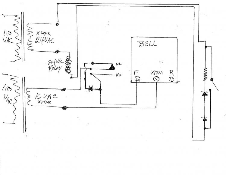
A new wired doorbell has been installed, specifically the Heath/Zenith Model #LE-65-B (Electronic). A new 16 Volt transformer was also added, along with a lighted pushbutton and a diode. Initially, all components functioned correctly, including the lighted pushbutton. However,...

This simple circuit can be used to protect a bike from theft. It produces a loud alarm tone if someone attempts to start the bike. The alarm can only be disabled when the hidden switch S2 is opened. The...