
Stepper Motor Control No Microcontroller Needed
A stepper motor control circuit typically consists of several key components that facilitate the precise movement of the motor. The main components include a microcontroller or a dedicated stepper motor driver IC, which generates the control signals necessary for the motor's operation. The microcontroller sends pulses to the driver, determining the speed and direction of the motor's rotation.
The circuit also includes a power supply to provide the necessary voltage and current to the motor. The power supply specifications must match the requirements of the stepper motor to ensure efficient operation. Additionally, the circuit may incorporate limit switches or sensors to provide feedback on the motor's position, allowing for closed-loop control.
Furthermore, the control circuit may utilize H-bridge configurations to enable bidirectional control of the motor. This configuration allows the motor to rotate in both clockwise and counterclockwise directions by reversing the polarity of the voltage applied to the motor windings.
In summary, a stepper motor control circuit is essential for achieving precise motion control, and its design incorporates various components to ensure reliable and efficient operation.Stepper motor is a simple way to make a motion control with high precision. A stepper motor control circuit is needed to make stepper motor works. A stepper.. 🔗 External reference
Related Circuits
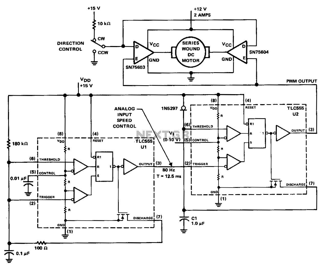
The PWM controller utilizes complementary half-H peripheral drivers SN75603 and SN75604, featuring totem-pole outputs rated at 40 V and 2.0 A. These drivers effectively configure the motor in a full-bridge setup, enabling bidirectional control. Timer U1 operates in astable...
The IC1A operational amplifier is configured as an inverting amplifier, with its gain determined by a three-way switch that connects different resistor values in parallel to R4. Following this input stage is an active three-band tone control circuit, designed...
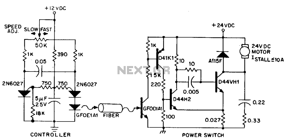
DC power can also be controlled using fiber optics. The circuit provides an insulated speed control path for a small DC actuator motor (less than Vn hp). The control logic is a self-contained module that requires approximately 300 mW...

This small device can be aimed at a television to jam the remote control signal. The circuit design is straightforward. A 555 timer is configured as an astable multivibrator operating at a frequency of approximately 38 kHz, which is...
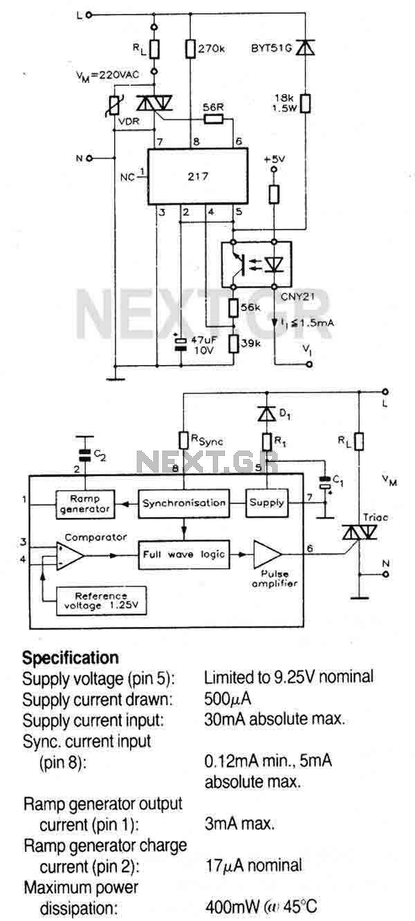
A triac controller for switching resistive loads directly from the mains supply using the zero crossing technique. The device is powered directly from the mains via a diode and dropper resistor, and the IC has its own regulator to...
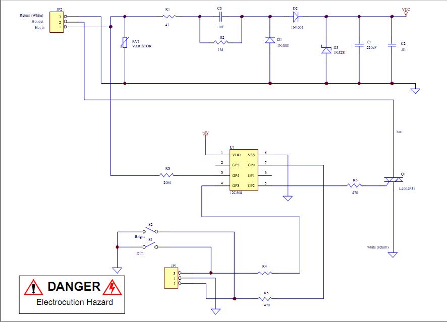
Assistance is required to modify a light dimmer circuit connected to a PIC12C508 microcontroller. This circuit is designed for the... The light dimmer circuit utilizing the PIC12C508 microcontroller serves to control the brightness of a light source through pulse width...