
Adjustable Timer
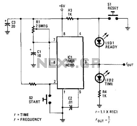
The described circuit utilizes two LED indicators to convey the operational status of a timer-based system. The reset switch, designated as SI, initiates the timer's state, which is maintained until the start switch, labeled S2, is engaged. This functionality allows for a clear visual representation of the timer's readiness and operational status.
LED1 serves as the "ready" indicator, illuminating when the circuit is primed for operation. Conversely, LED2 functions as a time indicator, signaling the active timing phase. The choice of color coding for these LEDs enhances user comprehension, with red typically associated with standby or readiness and green indicating that the timer is actively counting.
The circuit design should ensure that both LEDs are connected in parallel to the output of the respective switches, with appropriate current-limiting resistors included to prevent LED damage. The reset switch should be configured to momentarily ground the timer circuit, allowing it to reset to its initial state. The start switch, when pressed, should initiate the timing sequence while simultaneously illuminating LED2 to indicate that the timer is in operation.
For optimal performance, the circuit may include additional features such as debouncing for the switches to avoid false triggering, as well as a microcontroller or timer IC to manage timing functions. This would allow for more complex timing operations and enhanced functionality, such as adjustable timing intervals or additional status indicators. Overall, the design should prioritize clarity and user-friendliness, ensuring that the LED indicators provide immediate feedback regarding the status of the timer circuit. LEDs indicate at a glance what the status of the circuit is at any given moment. Once the reset switch, SI, makes contact, the timer remains in that state until the start switch, S2, is pressed. When either switch is activated, LED1 (ready) and the time indicator, LED2, keep track of the situation. Although not necessary, the two LEDs should be of different colors (for example, red for "ready" and green for "time").
🔗 External reference
Related Circuits
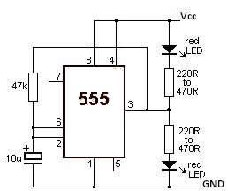
This LED flasher circuit utilizes a 555 timer integrated circuit (IC). The circuit diagram is straightforward and requires only a few external components. When operational, the red LEDs will flash sequentially at a predetermined frequency, similar to the indicators...
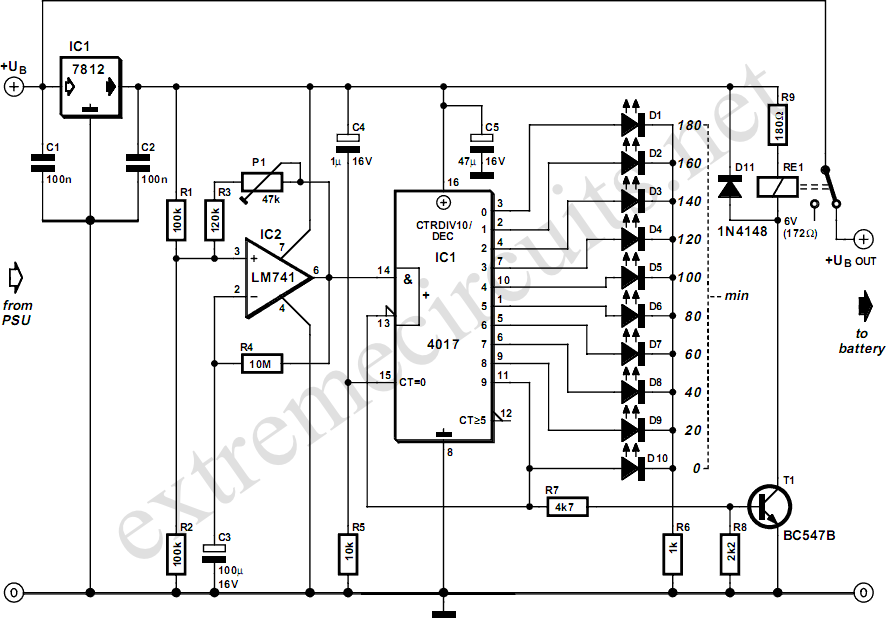
Manufacturers of cordless drills typically recommend a battery charging time of three hours. After this time, the battery should be disconnected from the charger to prevent the risk of overcharging. The following circuit is designed to prevent this scenario...
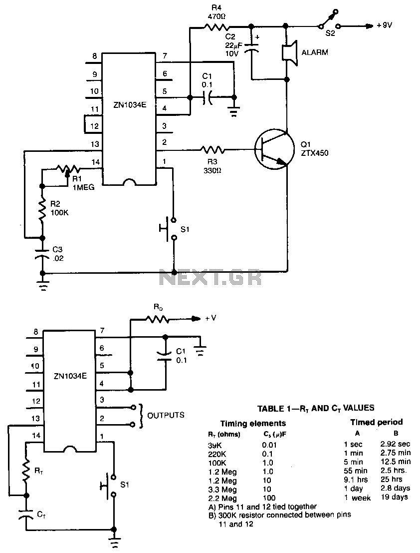
When used as a stand-alone device, the ZN1034E from Ferranti can provide timed intervals ranging from 1 second to 19 days, although the RC time constant is only 220 seconds. The ZN1034E includes an internal voltage regulator, an oscillator,...
This may appear to be a highly detailed post; however, it is being written to assist others who are experiencing a similar frustrating search for 12V timers that possess functionalities comparable to those found in mains timers. The intention...
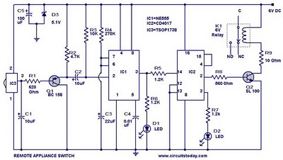
555 Timer TV Remote Controlled Home Appliance Circuit Diagram. Features: 555 timer IC to avoid fast switching. You can only switch the circuit. The 555 timer integrated circuit (IC) is a versatile component widely used in various electronic applications, including...
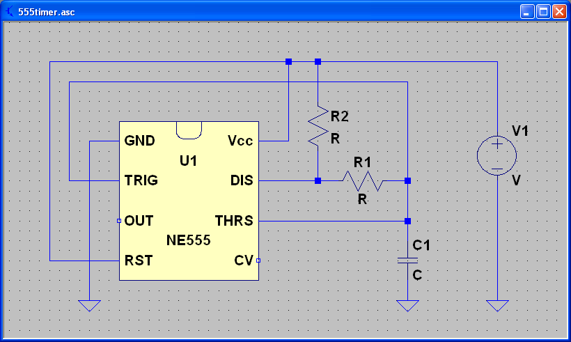
ECEN 2250 myDAQ Experiment Capacitors and the 555 Timer. The experiment involving capacitors and the 555 timer within the ECEN 2250 myDAQ framework focuses on understanding the behavior of capacitors in electronic circuits and the functionality of the 555 timer...