
555 timer led flasher circuit
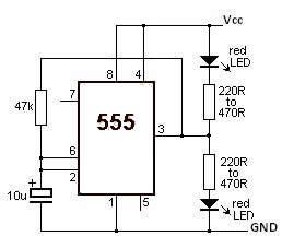
The LED flasher circuit employs the 555 timer in astable mode, allowing it to produce a continuous square wave output. This configuration is ideal for generating the flashing effect of the LEDs. The frequency of the flashing can be adjusted by varying the values of two resistors and a capacitor connected to the timer.
Typically, two resistors (R1 and R2) and one capacitor (C1) are used to set the timing intervals. The relationship between these components determines the rate at which the LEDs will flash. The output from the 555 timer is connected to a transistor, which acts as a switch to control the current flowing through the LEDs. This configuration ensures that the LEDs receive sufficient current to illuminate brightly while also allowing for efficient power management.
In addition to the basic components, a diode may be included in the circuit to prevent reverse polarity, ensuring the longevity of the timer and LEDs. The circuit can be powered by a standard DC voltage source, commonly ranging from 5V to 15V, depending on the specifications of the components used.
This design can be implemented in various applications, such as decorative lighting, warning signals, or any scenario where a flashing LED indication is required. The simplicity of the circuit makes it an excellent choice for beginners in electronics, as well as for more experienced engineers looking for a quick solution for LED flashing applications.This LED Flasher circuit is based on the 555 timer IC. The LED Flasher circuit diagram is very simple and require few external components. When the circuit is working the red LEDs will flash at a set frequency one by one like at the railway crossing indicator. 🔗 External reference
Related Circuits

To invoke the Spectrum +3 diagnostic routines, first reset the machine while holding the BREAK key down. This will bring up the test card display. Next, hold down the QAZMLP keys for a few seconds until the diagnostic title...
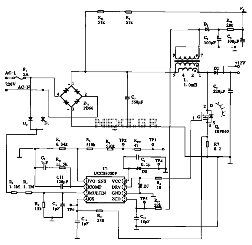
A typical laptop power adapter circuit converts an AC input of 22V through a rectifier and filter circuit to produce an output of +30V DC. This voltage is then processed by a switch oscillation circuit (U1, UCC38050P), which controls...
Fading a video signal cannot be achieved merely by attenuating the composite signal, as the synchronization signal may fall below an unacceptable level. Fading a video signal involves a careful adjustment of both the luminance and chrominance components while...
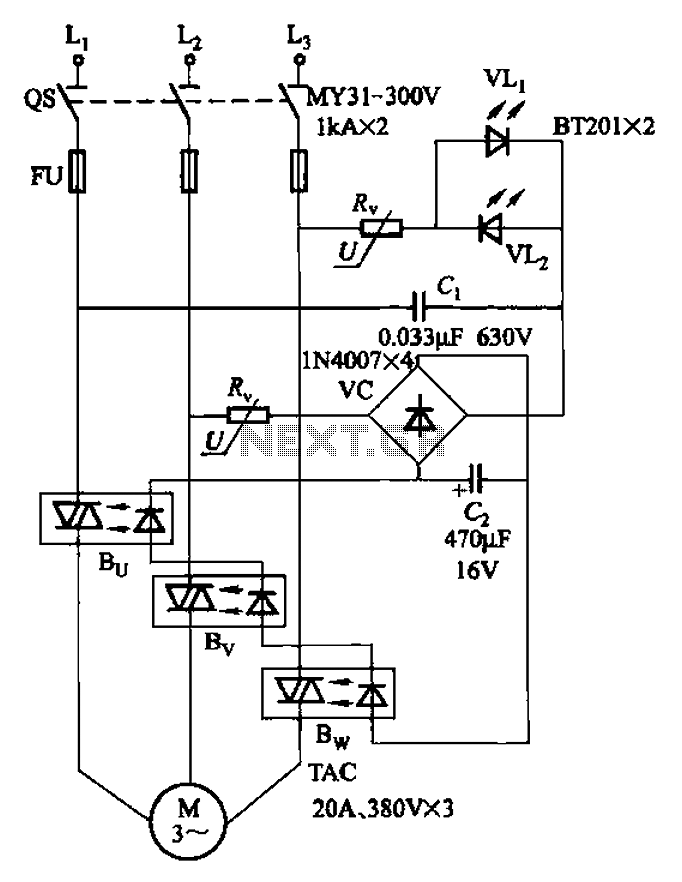
The circuit depicted in Figure 3-93 is integrated with an optical phase sequence protection relay. The circuit in question is designed to provide phase sequence protection using an optical relay mechanism. Optical phase sequence protection relays are crucial in applications...
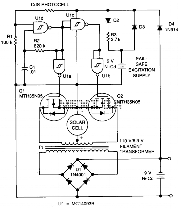
The circuit charges a 9-V battery at approximately 30 mA per input ampere at 0.4 V. U1, a quad Schmitt trigger, operates as an astable multivibrator to drive push-pull MOSFET devices Q1 and Q2. Power for U1 is derived...
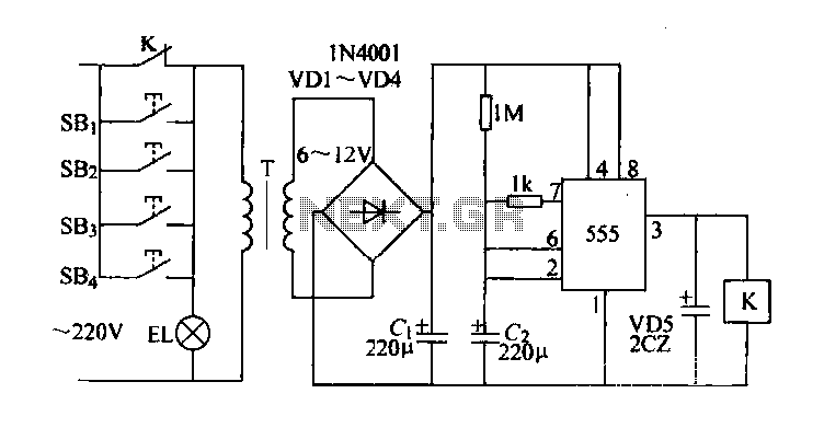
Control buttons SB1 to SB4 can be installed in various positions within a corridor. By pressing any one of these buttons, the EL horse lights will turn on. After releasing the button, the transformer and rectifier supply power to...