
Advanced Telephone Intercom


The circuit described operates as a sophisticated telephone switching system, allowing for two simultaneous calls while maintaining privacy. The Link 'P' architecture integrates several key components to achieve this functionality. The RTC (Ring Trip Circuit) is essential for managing incoming call signals, while the Reg. U (Register) functions as a selector for dialing. The STG (Service Tone Generator) provides the necessary audio feedback to the caller.
The addition of the LLO (Line Lock Out) ensures that only one phone can be active in the 'off hook' state, preventing multiple phones from engaging simultaneously. This is crucial for maintaining call privacy, as it directs any additional callers to a busy signal. The Vertical Control circuitry further enhances this by determining call precedence based on a simple logic rule.
The relay switching matrix, resembling a crossbar system, facilitates the routing of calls between the various phones connected to the system. The AND gate daisy chain mechanism monitors the status of each phone, ensuring that only one can transition to an active state when off hook. The flip flop configuration allows for the detection of this state change, enabling the appropriate relays and circuits to engage, thus facilitating the dialing process.
Upon dialing, the system processes pulses through the Reg. U, generating ring pulses that alert the called party. The use of capacitors within the circuit aids in resetting the system after each call, ensuring that it is ready for subsequent interactions. The integration of optocouplers allows for isolation and signal integrity, enhancing the overall reliability of the system.
This design effectively addresses common issues in multi-phone systems, such as simultaneous dialing conflicts, by implementing a structured approach to call management. The detailed circuit diagram referenced provides comprehensive information on component connections and configurations, essential for replicating or troubleshooting the system.In order to achieve a status between two levels of switching for two calls at the same time, you must first establish privacy on each call. Otherwise, you will end up with all four phones talking to each other, and that just won't do. So the Link 'P' is an intermediate stage between the basic Link design, and the fully blown one (yet to be realized, but not that far away,) with all the 'bells and whistles' features.
In the diagram above, you can see in block format, how this is achieved. The RTC (Ring Trip Circuit,) Reg. U (Register, which acts like an old style Uniselector,) and the STG (Service Tone Generator,) are all part of the basic Link design. However, I've added in two new 'blocks' of circuitry, and these are LLO (Line Lock Out, which provides busy tone back to callers who can't access the Link to make a call,) and Vertical Control (which governs who can and can't make a call - simple logic circuitry to determine who's first in and best dressed!) The relay switching matrix is akin to a simplified 'crossbar (XBAR) system. At the same time, the AND gate daisy chain 'sees' the chain broken by one of the four Q bar outputs going low, as the flip flop changes state, and this 'breaks the chain' thus making the output of the last AND gate in the chain change to a logic low.
This output at logic low, allows none of the other three phones to pick up 'off hook' and enable their LA relays. They cannot now gain access to the dial up level of the Link, unless they are the 'called party' whose number the caller will now dial into the REG U Register device (IC2.) Dial pulses are received via OC5 into IC2 pin 14, and the Link then operates as per normal.
Pin 3 of IC2 goes low, allowing C1 to charge up and produce Ring Pulses out of pin 9. This also enables IC1a to produce an interrupted Ring Tone into the 8R winding of TX via C3 and R6, coupling this signal to the calling party's phone. When both parties have hung up back to the 'on hook' status, the link P will reset itself due to capacitor C5 charging up, after the dialing loop has been broken, the two LEDS inside OC1 and OC2 have extinguished, and the two phototransistors have switched off.
The positive going pulse is sent to pin 15 of IC2 via diode D2, and to all four flip flop reset pins, so that the link P will be reset and waiting for the next call. There is a full circuit diagram spread over several pages later on in this article, which gives the details for connections and components for all four phones, and I will refer to these a little later on, but we'll just stick with the block diagram for now.
When a phone is picked up 'off hook' in the basic Link, it receives dial tone from the STG, and then the caller proceeds to dial a one digit number into the Register. This arrangement works well, except for those occasions when someone else picks their phone up 'off hook' at the same time, and tries to dial a number too.
The Link 'P' upgrade avoids this situation, by enabling only one phone in the 'off hook' state for the purposes of making a call, and if you are the first one to do so, you will be connected to the Reg. U and the STG. Any other caller will remain on Line Lock Out (LLO) and will receive Busy Tone, to indicate that the Link is busy with a call.
You can then dial any one of the other three phones, and the call will progress as per normal with the Link type circuitry. There are two methods of detecting a pickup of a phone into its 'off hook' status. The first is a simpler version, requiring no 'scanner' circuitry, and I will describe this briefly first.
With all four phones in their 'on hook' status (ie: hung up) all Q bar outputs of each individual flip flop are at logic high. Each of these outputs is monitored by an AND gate daisy chain, so that with all four outputs remaining high, the output of the last of the four AND gates will be a logic high too.
This logical outcome also appears on the collector lead of each line optocoupler (OC1 to OC4). When a caller picks up their phone off hook, they form a DC loop from +Vcc down through the LED of their line optocoupler, through the contacts of their LR and LA line relay contacts, through the phone handset, and down to ground via the 1K winding of transformer, BTX. The LED lights up and switches the internal phototransistor hard on, which then allows that line flip flop (FF1 to FF4) to operate their LA relay set, and this in turn, switches them to the dialing and service tone generation part of the Link 'P'.
The called party's phone will ring at around one ring per second (real 40 Volt AC ring this time, no more buzzers,) and when the called party picks their phone up 'off hook' to answer the call the RTC circuit will trip the ring, and they too, will be connected to the same level of the Link 'P' as the caller. Thus privacy will be maintained on all calls, and all other phones who are excluded from any particular call will receive a 'busy' signal, indicating that they need to try again a little later on.
🔗 External reference
Related Circuits
Here is a telephone line vigilant circuit to guard against misuse of your telephone lines. It monitors telephone lines round the clock and provides visual as well as an audio warning (when someone is using your telephone lines) which...
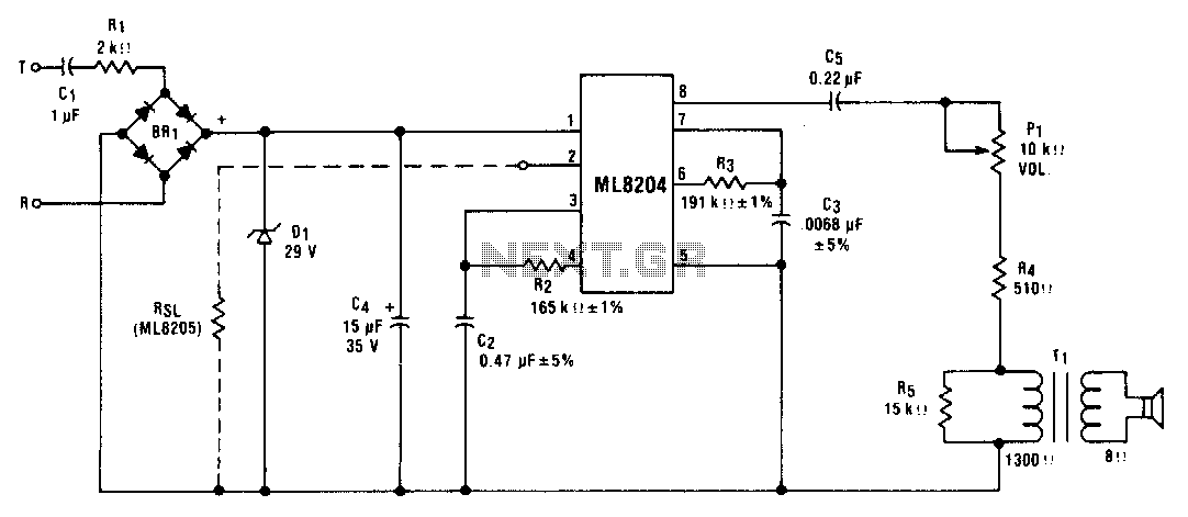
This circuit utilizes ML8204/ML8205 devices. The components illustrated result in an output frequency that oscillates between 512 Hz (fin) and 640 Hz (fb) at a modulation rate of 10 Hz (t). The circuit employing ML8204/ML8205 devices is designed for frequency...
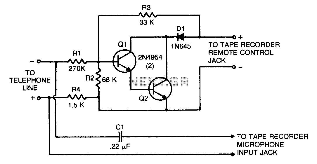
This circuit transforms a tape recorder into a fully automatic device for recording telephone conversations without requiring an external power source. The voltage at the switch terminals of the tape recorder is applied to a pair of Darlington-connected transistors,...
A teleremote circuit enables the switching on and off of appliances through telephone lines. It can be used to control appliances from any distance, overcoming the limited range of infrared and radio remote controls. The circuit can switch up...
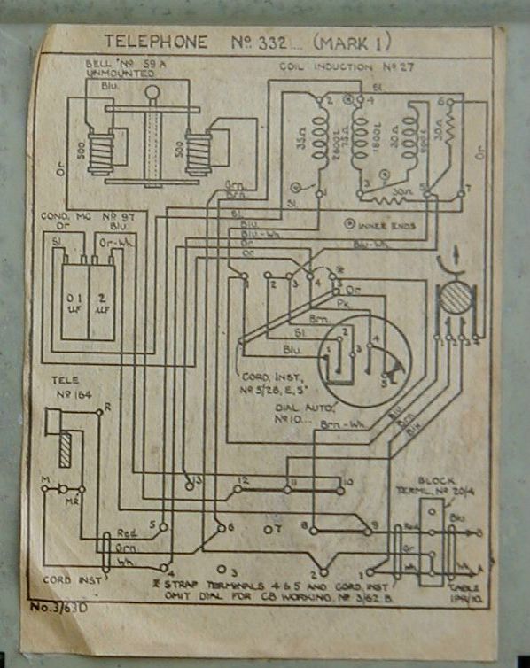
The induction coil is a component of the anti-sidetone circuit. It couples audio to the receiver and reduces the volume of the caller's own voice in the earpiece, which would otherwise be excessively loud compared to the incoming audio...
When a new computer modem is introduced into a home, the demand on the phone line increases significantly. Internet users can consume phone time similarly to a chatty teenager. Additionally, computer modem users often prioritize their privacy; for instance,...