
Remote control using telephone
Once a call is established (after hearing the ring-back tone), dialing 0 in DTMF mode causes IC1 to decode this as 1010, which is further demultiplexed by IC2 as output O10 (at pin 11). The active low output of IC2 is inverted by an inverter gate of IC3 (CD4049) to become logic 1. This logic level toggles flip-flop 1 (F/F-1), energizing relay RL1. Relay RL1 has two changeover contacts: RL1(a) provides a 220-ohm loop across the telephone line, while RL1(b) injects a 10kHz tone on the line, indicating that appliance mode has been selected. The 220-ohm loop disconnects the ringer from the telephone line, allowing for appliance mode operation. If digit 0 is not dialed in DTMF after establishing the call, the ringer continues, and the telephone can be used for normal conversation.
After entering appliance mode, dialing digit 1 is decoded by IC1, producing the output 0001. This BCD code is demultiplexed by IC2, and the corresponding output, after inversion by the CD4049 inverter gate, transitions to logic 1. This pulse toggles the corresponding flip-flop to an alternate state, and the flip-flop output drives relay RL2, which can switch on or off the connected appliance. Other appliances can similarly be controlled by dialing different digits.
To conclude the switching operation, the 220-ohm loop resistance and the 10kHz tone must be removed from the telephone line. This is achieved by dialing digit 0 again in DTMF mode, which toggles flip-flop 1 to de-energize relay RL1, terminating the loop on the line and disconnecting the 10kHz tone. The telephone line is then restored for normal calls. This circuit is designed to be connected in parallel to the telephone instrument.
This teleremote circuit is a versatile solution for remote appliance control, leveraging existing telephone infrastructure and DTMF signaling for operation. The use of a DTMF-to-BCD converter allows for straightforward interpretation of keypad inputs, while the demultiplexer and flip-flops facilitate the control of multiple appliances. The inclusion of relays provides the necessary isolation and control for high-voltage appliances, ensuring safe operation. Overall, this circuit exemplifies an innovative approach to remote control technology, effectively bridging telecommunications and appliance management.A teleremote circuit which enables switching on` and off` of appliances through telephone lines. It can be used to switch appliances from any distance, overcoming the limited range of infrared and radio remote controls. The circuit described here can be used to switch up to nine appliances (corresponding to the digits 1 through 9 of the te
lephone key-pad). The DTMF signals on telephone instrument are used as control signals. The digit 0` in DTMF mode is used to toggle between the appliance mode and normal telephone operation mode. Thus the telephone can be used to switch on or switch off the appliances also while being used for normal conversation.
The circuit uses IC KT3170 (DTMF-to-BCD converter), 74154 (4-to-16-line demult-iplexer), and five CD4013 (D flip-flop) ICs. The working of the circuit is as follows. Once a call is established (after hearing ring-back tone), dial 0` in DTMF mode. IC1 decodes this as 1010, ` which is further demultiplexed by IC2 as output O10 (at pin 11) of IC2 (74154).
The active low output of IC2, after inversion by an inverter gate of IC3 (CD4049), becomes logic 1. This is used to toggle flip-flop-1 (F/F-1) and relay RL1 is energised. Relay RL1 has two changeover contacts, RL1(a) and RL1(b). The energised RL1(a) contacts provide a 220-ohm loop across the telephone line while RL1(b) contacts inject a 10kHz tone on the line, which indicates to the caller that appliance mode has been selected. The 220-ohm loop on telephone line disconnects the ringer from the telephone line in the exchange. The line is now connected for appliance mode of operation. If digit 0` is not dialed (in DTMF) after establishing the call, the ring continues and the telephone can be used for normal conversation.
After selection of the appliance mode of operation, if digit 1` is dialed, it is decoded by IC1 and its output is 0001`. This BCD code is then demultiplexed by 4-to-16-line demultiplexer IC2 whose corresponding output, after inversion by a CD4049 inverter gate, goes to logic 1 state.
This pulse toggles the corresponding flip-flop to alternate state. The flip-flop output is used to drive a relay (RL2) which can switch on or switch off the appliance connected through its contacts. By dialing other digits in a similar way, other appliances can also be switched on` or off. ` Once the switching operation is over, the 220-ohm loop resistance and 10kHz tone needs to be removed from the telephone line.
To achieve this, digit 0` (in DTMF mode) is dialed again to toggle flip-flop-1 to de-energise relay RL1, which terminates the loop on line and the 10kHz tone is also disconnected. The telephone line is thus again set free to receive normal calls. This circuit is to be connected in parallel to the telephone instrument. 🔗 External reference
Related Circuits
This method of automatic level control (ALC) utilizes digitally switched audio attenuators within the signal path. The output level of the system is monitored, compared to a reference level, and audio pads are introduced through analog switches. This technique...
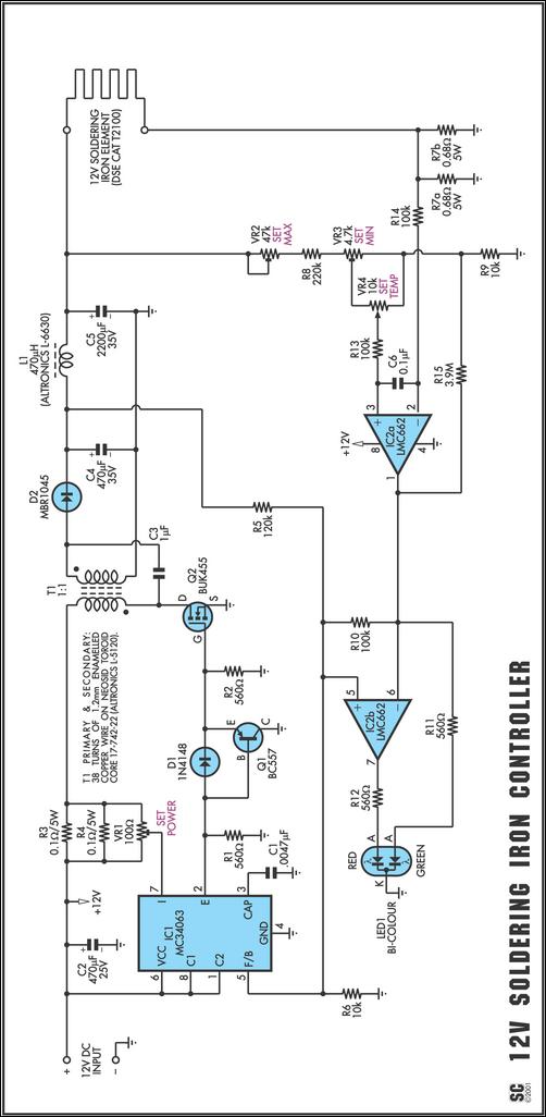
One reason commercial soldering stations are costly is that they typically require soldering irons with built-in temperature sensors, such as thermocouples. This circuit removes the necessity for a specialized sensor by detecting the temperature of a soldering iron heating...
A project is underway to control the speed of an electric fan (220Vac, 60W, 5A max.) automatically using a microcontroller based on certain parameters. The circuit design for controlling the speed of an electric fan involves several key components to...
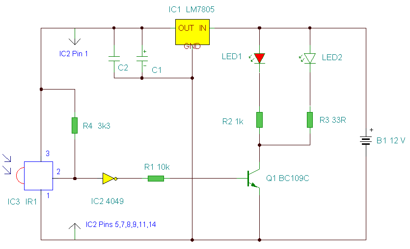
This is an improved IR remote control extender circuit. It has high noise immunity, is resistant to ambient and reflected light and has an increased range from remote control to the extender circuit of about 7 meters. It should...
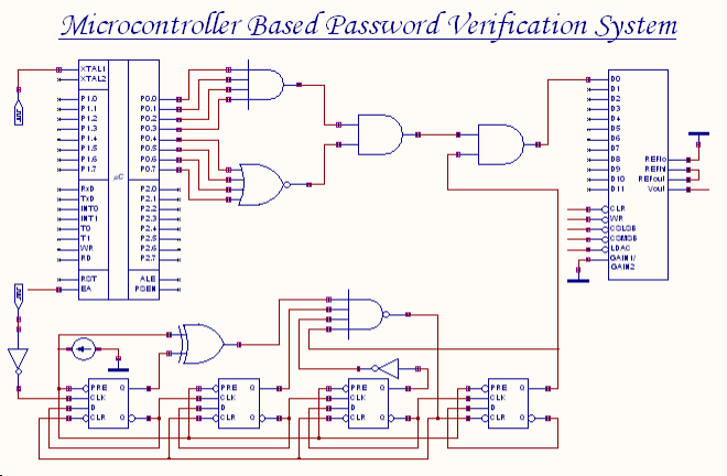
An 8-bit password serves as the input to this system. The password entered by the user is compared with the actual password, which is set in the microcontroller through a microprogram. The outcome of this comparison process generates an...
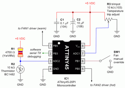
Here is a circuit diagram designed for DIY enthusiasts who aim to construct a dual fan controller utilizing an ATtiny45 microcontroller. The circuit activates the first fan when the temperature reaches a user-adjustable dial setting and engages a second...