
telephone line loger
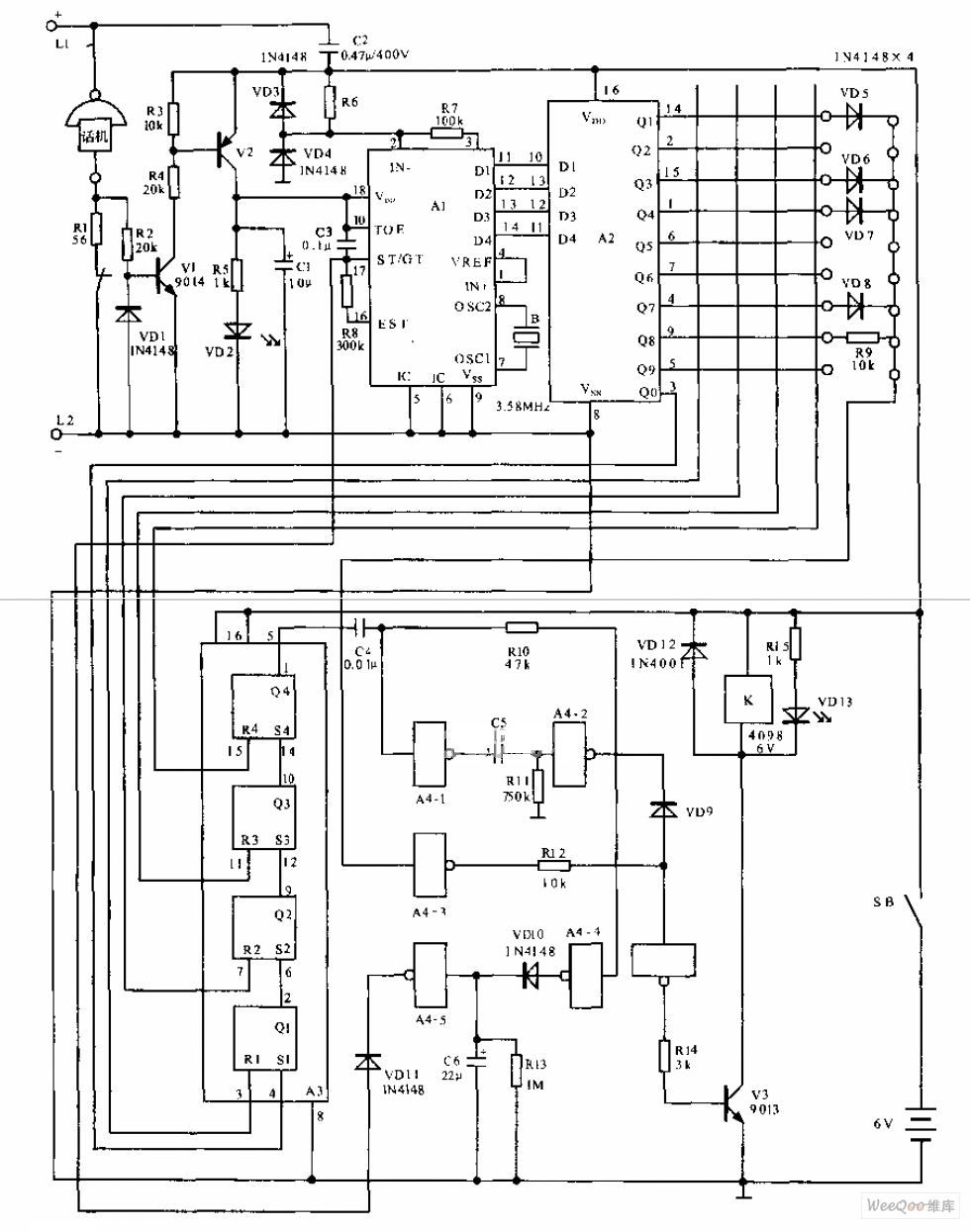
Irrespective of telephone line polarity at the input to the circuit, proper DC polarity is maintained across C1 due to bridge rectifier comprising diodes D1 to D4. The DC voltage developed across capacitor C1 is used to check telephone line condition as per Table I. This circuit draws negligible current from the telephone line; thus when it is connected to the telephone line, the normal telephone operation is not affected. The circuit may be divided into two parts. The first part comprises zener D9, transistors T1 to T4 and diode D5. It is used to verify whether telephone line loop is intact or discontinuous. The second part comprising zener D10 and transistors T5 to T10 is used to check whether telephone line is in use (or misuse) or not. The zener diode D9 (3.3V) conducts when phone line loop is intact and not broken. Zener D9 sets control voltage for transistors T1, T2 and T3 to conduct and for T4 to cut off. As a result, green LED lights but no sound is heard from the buzzer.
When phone line loop is discontinuous, no voltage is available across capacitor C1. Thus zener D9 and transistors T1, T2 and T3 do not conduct while T4 conducts. Now green LED extinguishes and a continuous sound is heard from the buzzer. When telephone line is alright but is not in use, zener D10 conducts as voltage across capacitor C1 is quite high. This results in conduction of transistors T5 and T6 and cutting off of transistor T7 (as collector of transistor T6 is near ground potential). Thus positive 9V rail is not extended to the following multivibrator circuit built around transistors T8 and T9. Consequently, the red LED is not lit and buzzer does not sound. When phone line is in use, zener D10 does not conduct. As a result, transistors T5 and T6 also do not conduct, while transistor T7 conducts. Now +9V is extended to the multivibrator circuit. This multivibrator is designed such that collector of transistor T9 goes high once every 5 seconds to forward bias transistor T10 and it conducts. Thus at every 5-second interval a beep sound is heard from the buzzer. The beep sound interval can be increased or decreased by changing the value of capacitor C3 while the volume can be adjusted with the help of preset VR3.
The circuit operates by utilizing a bridge rectifier formed by diodes D1 through D4, which ensures that the correct DC polarity is maintained across capacitor C1 regardless of the input polarity from the telephone line. The output from C1 feeds into a monitoring system that includes zener diodes and transistors, which are configured to detect the status of the telephone line. The zener diode D9 serves as a critical component for detecting line integrity; it activates when the line is intact, allowing current to flow through transistors T1, T2, and T3, illuminating the green LED and silencing the buzzer. Conversely, if the line is broken, the lack of voltage across C1 prevents D9 from conducting, resulting in T4 being activated, which turns off the green LED and triggers the buzzer.
The second part of the circuit, governed by zener diode D10, assesses whether the line is currently in use. If the line is idle, D10 conducts, allowing T5 and T6 to turn on while T7 remains off, preventing any voltage from reaching the multivibrator. If the line is in use, D10 does not conduct, allowing T7 to activate and send voltage to the multivibrator circuit, which intermittently triggers the buzzer at a 5-second interval. The timing of the beeps can be adjusted by modifying capacitor C3, while the buzzer's volume can be fine-tuned using the variable resistor VR3, providing flexibility in the circuit's operation. This vigilant circuit is designed to be unobtrusive while effectively monitoring the telephone line, ensuring that any unauthorized use or line interruptions are promptly detected. Here is a telephone line vigilant circuit to guard against mis- use of your telephone lines. It monitors telephone lines round the clock and provides visual as well as an audio warning (when someone is using your telephone lines) which can be heard anywhere in the house. Another advantage of using this circuit is that one comes to know of the misuse and snapping of the lines (due to any reason) instantaneously on its occurance.
This enables the subscriber to take necessary remedial measures in proper time. Even when the subscriber himself is using his telephone (handset off-cradle) while the vigilant circuit is on, the buzzer beeps once every 5 seconds since the vigilant circuit cannot distinguish between self-use of the subscriber lines or by any unauthorised person. Thus to avoid unnecessary disturbance, it is advisable to install the vigilant unit away from the phone.
However, if one wishes to fit the unit near the telephone then switch S1 may be flipped to off position to switch off the buzzer. But remember to flip the switch to on position while replacing the handset on cradle. Irrespective of telephone line polarity at the input to the circuit, proper DC polarity is maintained across C1 due to bridge rectifier comprising diodes D1 to D4.
The DC voltage developed across capacitor C1 is used to check telephone line condition as per Table I. This circuit draws negligible current from telephone line; thus when it is connected to the telephone line, the normal telephone operation is not affected.
The circuit may be divided into two parts. The first part comprises zener D9, transistors T1 to T4 and diode D5. It is used to verify whether telephone line loop is intact or discontinuous. The second part comprising zener D10 and transistors T5 to T10 is used to check whether telephone line is in use (or misuse) or not. The zener diode D9 (3.3V) conducts when phone line loop is intact and not broken. Zener D9 sets control voltage for transistors T1, T2 and T3 to conduct and for T4 to cut off. As a result, green LED lights but no sound is heard from the buzzer. When phone line loop is discontinuous, no voltage is available across capacitor C1. Thus zener D9 and transistors T1, T2 and T3 do not conduct while T4 conducts. Now green LED extinguishes and a continuous sound is heard from the buzzer. When telephone line is alright but is not in use, zener D10 conducts as voltage across capacitor C1 is quite high.
This results in conduction of transistors T5 and T6 and cutting off of transistor T7 (as collector of transistor T6 is near ground potential). Thus positive 9V rail is not extended to the following multivibrator circuit built around transistors T8 and T9.
Consequently, the red LED is not lit and buzzer does not sound. When phone line is in use, zener D10 does not conduct. As a result, transistors T5 and T6 also do not conduct, while transistor T7 conducts. Now +9V is extended to multivibrator circuit. This multivibrator is designed such that collector of transistor T9 goes high once every 5 seconds to forward bias transistor T10 and it conducts. Thus at every 5-second interval a beep sound is heard from buzzer. The beep sound interval can be increased or decreased by changing the value of capacitor C3 while the volume can be adjusted with the help of preset VR3.
🔗 External reference
Related Circuits
A smart card is designed using EEPROM chips, while smart card readers utilize a Renesas microcontroller. The card reader reads data from the smart card and transmits it to a computer via its serial port. Access is granted only...

A repertory dialer phone contains a library of phone numbers that can be entered and dialed, allowing access to up to fifteen frequently used numbers. It also includes the capability to store the last dialed number or an additional...
This circuit functions as an RF power amplifier designed to operate with a power supply capable of delivering 13 volts at a current of 10 amperes. Careful assembly of the power source is essential. It utilizes a shielded transformer...
The telephone electronic coded lock circuit is designed for double audio circuits. When this coded lock is installed on a phone, dialing out requires the user to input a four-digit pre-programmed password using the phone's buttons. If the password...
Audio from a telephone line can be obtained using a transformer and capacitor to isolate the line from external equipment. A non-polarized capacitor is placed in series with the transformer line connection to prevent DC current from flowing in...

The gate drive that phase controls the four parallel SCRs is achieved using a complementary MOS hex gate MC14572 and two bipolar transistors. This adjustable line-synchronized driver allows SCR conduction from near zero to 180 degrees. A Schmitt trigger...