
Af Power Oscillator Circuit
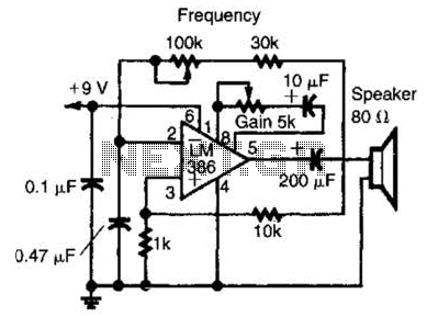
The LM386 is a low-voltage audio power amplifier that is commonly utilized in various audio applications. In this configuration as a feedback oscillator, it takes advantage of its gain characteristics to produce oscillations. The circuit typically includes a few additional components such as resistors, capacitors, and possibly a diode, which help to establish the feedback loop necessary for oscillation.
The supply voltage range of 6 to 12 V allows for flexibility in power source selection, making it suitable for battery-operated devices or other low-voltage applications. The feedback mechanism can be adjusted by varying the resistor and capacitor values, which will influence the frequency and amplitude of the oscillation produced.
When driving a loudspeaker, the output stage of the LM386 provides sufficient power to drive small to medium-sized speakers effectively. The output signal can be further filtered or modified using additional passive components to shape the audio output according to specific requirements.
In summary, this circuit design utilizing the LM386 as a feedback oscillator is a versatile solution for generating audio signals, capable of driving a loudspeaker within the specified voltage range. An LM386 audio power IC is set up as a feedback oscillator. Any supply from 6 to 12 V can be used. The circuit can drive a loudspeaker. 🔗 External reference
Related Circuits
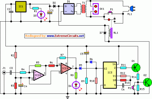
This circuit turns off an amplifier or any other device when a low-level audio signal fed to its input is absent for at least 15 minutes. Pressing P1 switches the device on, supplying power to any appliance connected to...
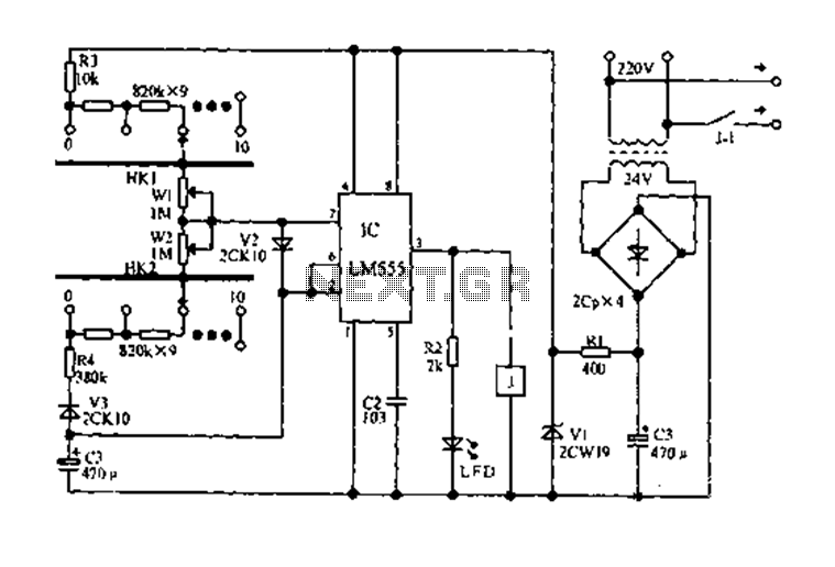
The circuit diagram for an electric start and stop timer is illustrated in the following cycle. It utilizes the LM555 integrated circuit configured as an adjustable duty cycle multivibrator. The circuit includes components C3, KH1, W1, KH2, and W2,...
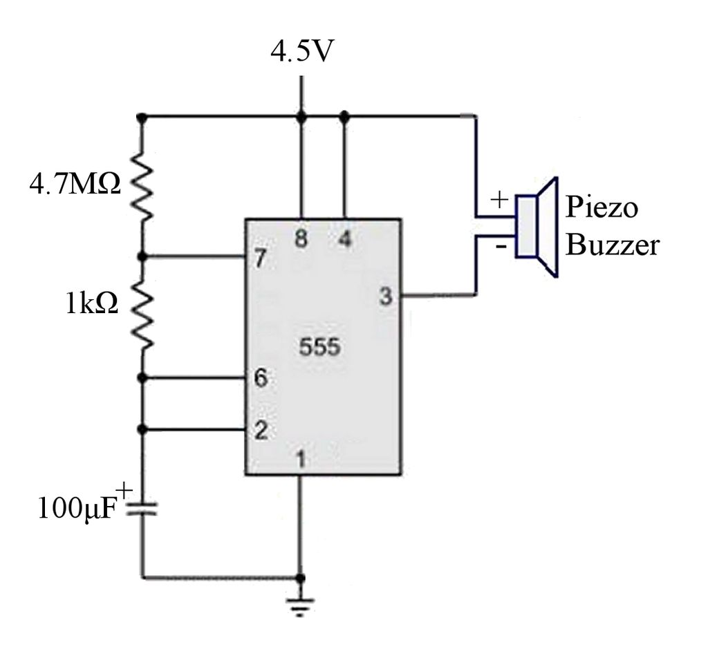
The circuit is a basic 555 timer circuit in astable mode. In this configuration, the integrated circuit (IC) generates a brief pulse to the buzzer at regular intervals. The 555 timer in astable mode operates as an oscillator, producing a...
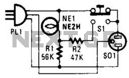
If residing in a cold climate, it is reassuring to confirm the functionality of an engine-block heater. This device indicates whether the heater is operational. To use, connect PL1 to a power outlet; the NE1 indicator should illuminate. Next,...
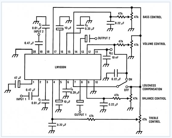
The LM1036 is a DC-controlled tone (bass/treble), volume, and balance circuit designed for stereo applications in car radios, televisions, and audio systems. It features an additional control input that facilitates loudness compensation. Four control inputs enable the adjustment of...
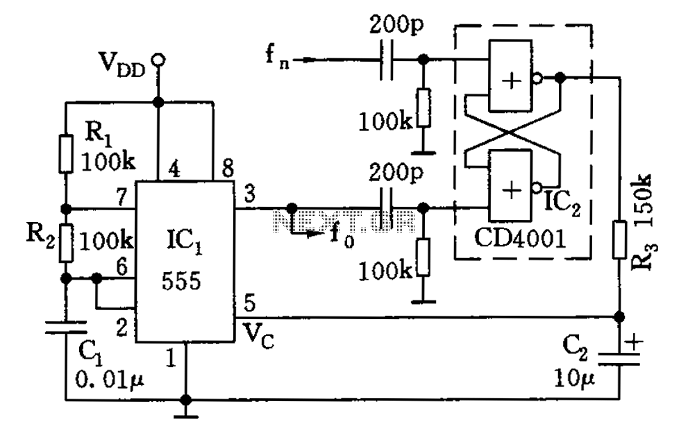
The circuit illustrated consists of a 555 timer along with resistors R1 and R2, and capacitor C1, forming a composition-controlled multivibrator. The oscillation frequency is influenced not only by the RC time constant but also by the adjustment of...
Warning: include(partials/cookie-banner.php): Failed to open stream: Permission denied in /var/www/html/nextgr/view-circuit.php on line 713
Warning: include(): Failed opening 'partials/cookie-banner.php' for inclusion (include_path='.:/usr/share/php') in /var/www/html/nextgr/view-circuit.php on line 713