
Air flow detector circuit
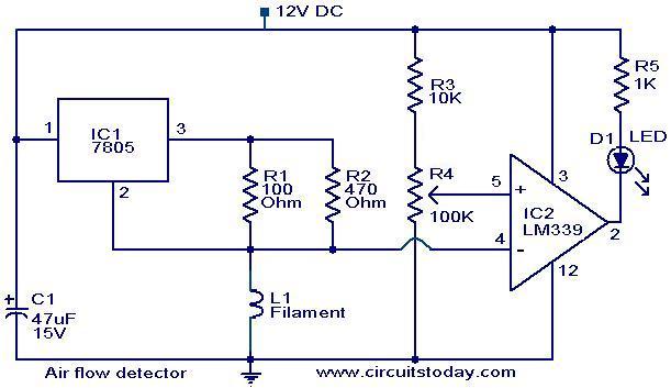
The circuit employs an incandescent bulb filament as a temperature-sensitive resistor, utilizing its positive temperature coefficient (PTC) characteristic. The principle of operation is based on the relationship between temperature and resistance in the filament. When a constant current flows through the filament, it heats up, and its resistance decreases. If airflow is present, it cools the filament, causing the resistance to drop further. This change in resistance alters the voltage across the filament, which is monitored by the LM339 operational amplifier configured as a comparator.
The LM339 compares the voltage drop across the filament to a reference voltage. When the filament cools due to airflow, the voltage drop decreases, which causes the output of the LM339 to change state, affecting the brightness of the connected LED. If the LED is intended to indicate high airflow, the configuration of the comparator can be adjusted by swapping the inverting and non-inverting inputs.
The current source for the filament can be implemented using a voltage regulator, such as the IC 7805, which provides a stable output to ensure consistent heating of the filament. The circuit design must ensure that the filament operates within its optimal resistance range for effective airflow detection.
Applications of this airflow detector include monitoring ventilation systems, ensuring adequate cooling in electronic devices, and optimizing the performance of HVAC systems. Enhancements for real-time applications may involve integrating digital output for microcontroller interfacing, employing more sensitive sensors for improved accuracy, or using alternative materials with similar PTC characteristics for better performance. Overall, this project can serve as an educational platform for understanding the principles of thermoresistive sensing and its applications in environmental monitoring.The filament of a incandescent bulb is the sensing part of the circuit. When there is no air flow the resistance of the filament will be low. When there is air flow the resistance drops, because the moving air will remove some of the heat generated in the filament. This variations in the resistance will produce variation of voltage across the filame nt. These variations will be picked up by the opamp (LM339) and the brightness of the LED at its output will be varied proportionally to the airflow. The current source should be capable of supplying 50mA to the filament. around 80 to 100 ohms in value. if your filament resistance is more than 100 ohms this circuit will not work. you have to use portion of the bulb filament instead of full length. use around 50 to 60 ohms of it. Dear Seetharaman, i am doing a project very similar to this. It is like im using a wind flow sensor. Is there any way that you could help me with this please Thanks in advance Air flow detector is user to find the adequate air flow in a system.
(may be a bower or a cooling fan air flow) Here the positive temperatue coefficient charecterestic of the bulb filament is used for detecting the air flow(the air flow will cool the bulb filament (which is heated by constant current flow through it). Once the air flow decreases the bulb temperature will increase its resistance will increase which will detected and indicated by the LED.
I am making this project in my college and i am required to submit the report but due to lack of adequate information i am unable to make the report. so kindly help me by providing some more information on this topic or your report on this project. Thankyou. Hi Sir, i am doing a project on air flow detector and i have to submit a report on that but i dont have enough information to make the report.
So i request you to give some more information about the project or post your own report. It would be of great help for us. Thankyou. Hai sir, i want to know the complete info that how much amount of air this circuit detects. and added that what is the replacement for filament in this circuit. how can i enhance this circuit in real time applications. ive chosen this as my mini project in this sem. so please send all these informations to my mail soon. thank u very much can u give me the detail information about application of air flow detector and where it is mainly used . plz give me the answer, im doing mini project on this topic sir . sir i want to know more details about this project. i am very eager to know dis. so please send me more information about (principle, construction, each elements work) to my mail ID.
thank u sir . Air flow detector is user to find the adequate air flow in a system. (may be a bower or a cooling fan air flow) Here the positive temperatue coefficient charecterestic of the bulb filament is used for detecting the air flow(the air flow will cool the bulb filament (which is heated by constant current flow through it). Once the air flow decreases the bulb temperature will increase its resistance will increase which will detected and indicated by the LED.
Hi Ireti The IC 7805 forms a 60mA constant current source feeding the filament. The voltage drop across it is compared by the comparator IC and the ouput is produced. Normally cold bulb filament resistance is low(a positive temperature coefficient material) as it gets heated up the drop across the filament increases due to which the LED goes on. when the filament senses air flow the heat is removed hence the resistance falls down, due to which the LED goes off.
If you want the operation other way, air more than a particular flow to indicate by LED going on, interchange comparator ICs inv and non inv port (4 & 5) sir i want to know more details about this project. i am very eager to know dis. so please send me more information about (principle, construction, each elements work) to my mail ID.
thank u 🔗 External reference
Related Circuits
This document presents plans for a simple ground plane antenna that is effective in the FM band (88-108 MHz). It is constructed from a small plastic disk. The 6 x 6 loop antenna, designed by Graham Maynard, is highlighted...
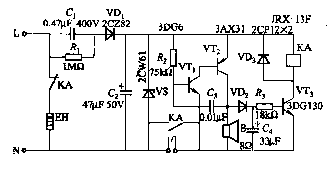
When the water boils, it not only triggers the police but also cuts off the heater power. A temperature sensing element is integrated with a fluorescent neon light bulb, which is restructured within the starter. The described circuit features a...
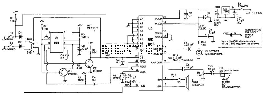
The circuit utilizes an ISD1016 audio record/playback chip from Information Storage Devices, Inc. to record and playback messages on demand. While it is primarily designed for use with transmitters, it can also serve as an electronic notepad or similar...

This circuit is a robust and efficient power amplifier suitable for various audio applications. It delivers 60W RMS output at a 50V supply with an 8 Ohm load. The design is user-friendly, allowing for the use of non-critical components...
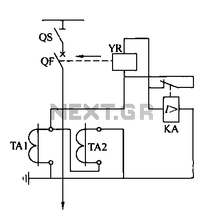
Operating power protection devices can be categorized into two types: DC power supply operation and AC operation. AC operating power is favored due to its lower investment costs, simpler operation, and reliable secondary circuit maintenance, making it widely used...
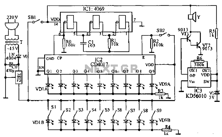
This document presents a principle circuit for electronic games. The main circuit operates in conjunction with the host through the reset button SB2, while the indicators VD1A-VD9A remain off. Prizes, for example, five, are determined by the number of...
Warning: include(partials/cookie-banner.php): Failed to open stream: Permission denied in /var/www/html/nextgr/view-circuit.php on line 713
Warning: include(): Failed opening 'partials/cookie-banner.php' for inclusion (include_path='.:/usr/share/php') in /var/www/html/nextgr/view-circuit.php on line 713