
Antenna Circuits / Schematics
The design of the ground plane antenna is straightforward, utilizing a plastic disk as the base. The antenna's effectiveness in the FM band is attributed to its simple yet effective geometry, which allows for a broad frequency response. The loop antenna's aperiodic nature ensures that it can capture a wide range of frequencies, making it versatile for various applications.
The AA-7 active antenna is particularly beneficial for users with limited space, providing enhanced reception capabilities. Its design allows it to outperform traditional short antennas, making it suitable for environments where long antennas cannot be installed. The compact size and efficiency of this active antenna make it an excellent choice for both amateur and professional radio enthusiasts.
The dipole antenna, while simple, is an effective solution for improving FM signal reception. Its directional characteristics allow users to focus on specific signal sources, enhancing overall performance. The inclusion of E-field circuits emphasizes the need for proper impedance matching to ensure optimal signal amplification and minimize losses due to cable capacitance.
In addition, the construction of the ground pole antenna and half-wave dipole antenna highlights the importance of material selection and design considerations. The use of aluminum rods ensures durability and effective signal transmission. The integration of a 75-ohm cable facilitates compatibility with standard receivers, further enhancing usability.
Overall, these antenna designs and circuits provide a comprehensive toolkit for enhancing radio reception across various bands, catering to a wide range of user needs and environmental constraints.Here you can find plans for a simple ground plane antenna that works well in the FM Band (88-108MHz). It`s built of a small plastic disk 6 x 6 Loop Antenna - This new loop antenna by Graham Maynard is his best design yet and I am proud to be the first to present his work.
It uses one, six foot square, six turn loop , and is aperiodic in nature, covering the frequency range 50KHz - 5000KHz. Active Antenna AA-7 HF/VHF/UHF, 3-3000MHz - If you have a shortwave or high-frequency receiver or scanner that is struggling to capture signals with a short, whip antenna, and you`d like the kind of performance that a 60-foot `longwire` antenna can provide but lack the space to put one up, consider building the AA-7 HF/VHF/UHF Active Antenna described in this article. Active Antenna for AM-FM-SW - This simple little circuit can be used for AM, FM, and Shortwave(SW). On the shortwave band this active antenna is comparable to a 20 to 30 foot wire antenna. It is further more designed to be used on receivers that use untuned wire antennas, such as inexpensive units and car radios.
Active Antenna, easy to build - When fate or nasty neighbours prevent you from stringing a long-wire receiving antenna, you`ll find that this pocket-size antenna will give the same, or even better, reception. This "Active Antenna" Dipole Antenna - A simple dipole antenna can be used for improved FM broadcast signals.
A dipole is basically a length of conductor (wire) split into two portions and signal is taken off at the split. It has a nominal 3 dB gain over an isotropic source and is directional, tending. E-field Circuits - If you place the amplifier at the antenna, you avoid all that cable capacitance but your amplifier must have a correspondingly higher input impedance to maintain flat gain at the lower frequencies.
For a typical 10 pF antenna (about a meter long) you would want a 100 megohm input impedance to have flat gain down to 150 Hz! One simple solution is to add some shunt capacitance across the antenna, eating. Ground Pole Antenna - This Antenna is most widely used all over the world. For example, when you see a police car it has a transmitter with Ground Pole Antenna The body of car serves as ground).
It accepts load from 50 ohm source and has larger power output than Half-Wave Dipole Antenna. Half-Wave Dipole Antenna (Open Dipole) - It accepts load from 75 ohm source and has much smaller power output than Ground Pole Antenna. Use this antenna only when you don`t have GP Antenna. Construction: Two aluminium rods, each of length "L" in meters are joined together through an insulator as shown in fig.
From center, 75 ohm cable is feeded just like ordinary TV antenna. Medium Wave Active Antenna - This circuit is designed to amplify the input from a telescopic whip antenna. The preamplifier is designed to cover the medium waveband from about 550Khz to 1650Khz. The tuning voltage is supplieb via RV2, a 10k potentiometer connected to the 12 Volt power supply. 🔗 External reference
Related Circuits
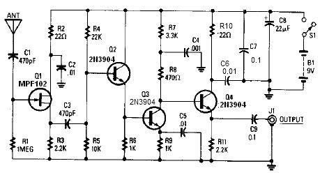
A simple active antenna can be designed using this electronic circuit diagram. This active antenna utilizes transistors and a few common electronic components. In the practice of short-wave frequency reception, a general rule is that a longer antenna will...
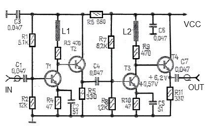
This antenna amplifier is effective for the frequency range of 35 kHz to 150 MHz. The circuit utilizes transistors and features a low 3 dB non-linearity along with a high gain of 43 dB. The input and output impedance...
The basic two-transistor flasher has become widely utilized in various applications due to its simplicity and versatility. It has been employed in circuits such as a micropower low battery indicator, a lightning detector, an off-line switching power supply, a...
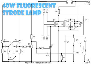
This circuit is designed for a 40 Watt fluorescent lamp. It operates similarly to a traditional strobe light, but utilizes a fluorescent tube instead. The fluorescent tube remains continuously energized, with both electrodes supplied with electricity. This current causes...
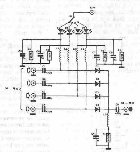
This antenna selector circuit diagram utilizes PIN diodes, which address the drawbacks of mechanical switches, particularly in high-frequency current applications. PIN diodes are well-suited for this purpose due to their linear resistance characteristics across a wide range of current...
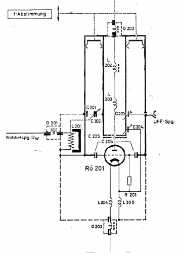
The use of a quarter-wave parallel-wire line as a tuning unit has been discussed in the chapter on Short Lines, where it was pointed out that these circuits have comparatively high Q even at higher frequencies. Their great length...
Warning: include(partials/cookie-banner.php): Failed to open stream: Permission denied in /var/www/html/nextgr/view-circuit.php on line 713
Warning: include(): Failed opening 'partials/cookie-banner.php' for inclusion (include_path='.:/usr/share/php') in /var/www/html/nextgr/view-circuit.php on line 713