
air flow sensor circuit

The circuit utilizes the PIC16C781 microcontroller as the central processing unit, which manages the operation of the Programmable Switch Mode Controllers (PSMC). The PSMC integrates various components that work together to ensure accurate and efficient air flow sensing. The primary sensing mechanism relies on the thermal properties of the RTDs, R5 and R7, which respond to temperature changes caused by air flow. When air moves across the heated resistor, it cools the resistor, leading to a measurable change in resistance that the microcontroller can interpret.
The operational amplifier (Op Amp) plays a crucial role in amplifying the voltage signals generated by the RTDs. The configuration of the voltage dividers, R2-R5 and R1-R7, ensures that the Op Amp receives a balanced input even when the ambient temperature fluctuates. This balance is critical for maintaining the accuracy of the flow measurements, as it mitigates the effects of temperature variations on the sensor's output.
The Digital-to-Analog Converter (DAC) provides a variable reference voltage that adjusts according to the operational requirements of the circuit. This adaptability allows the system to maintain optimal performance across different environmental conditions. The gated timer incorporated into the design enables precise timing control, ensuring that the sensor operates efficiently and responds quickly to changes in air flow.
Overall, this air flow sensing circuit exemplifies a sophisticated integration of microcontroller technology with analog components, resulting in a reliable and efficient sensor suitable for various applications in environmental monitoring and automation systems.This circuit is describes about sensing air flow using microcontroller PIC16C781. In this circuit is using Programmable Switch Mode Controllers (PSMC) that combination between the Integrated Operational Amplifier, Digital-to-Analog Converter (DAC), and gated timer to construct a thermally operated air flow sensor with minimum external components. This is the figure of the circuit. Air flow is detected by the cooling effect of air movement across a heated resistor. R5 and R7 are thin film platinum Resistance Temperature Detectors (RTD). These are essentially thermistor with a very linear temperature response. The flow sensor is comprised of R6 and R7. Changes in ambient temperature conditions are compensated by two voltage dividers, R2-R5 and R1-R7. R2 and R5 form a voltage divider between the Op Amp output and the Op Amp inverting input. Similarly, R1 and R7 form a voltage divider between the variable DAC reference and the non-inverting Op Amp input. Since R5 and R7 are identical RTD`s, resistance variations due to self heating, as well as changes in the ambient conditions, cancel out at the Op Amp inputs.
[Schematic source: Microchip Technology Inc]. 🔗 External reference
Related Circuits
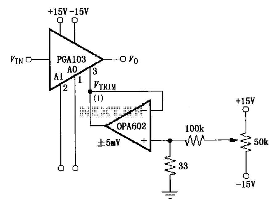
The PGA103 offset voltage correction circuit is designed to minimize the offset voltage for the PGA103 laser correction, ensuring that the gain for three typical offset voltage levels (relative to input) remains below 200 V. Each gain is associated...
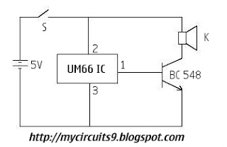
This is a circuit diagram for a simple doorbell. The circuit can be assembled indoors, while the switch should be placed outside, making it easily noticeable for visitors. The operation of this circuit is similar to a previous project. The...
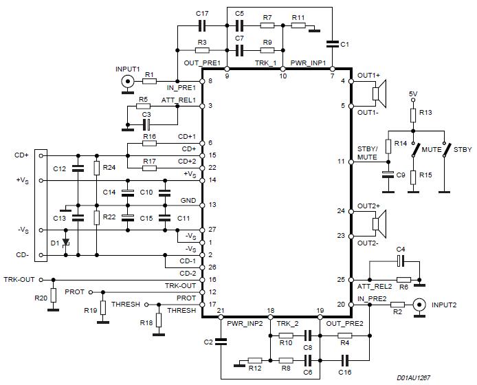
The Stereo Power Amplifier utilizes a 2x70Watt STA550 chip designed for audio power applications, featuring a BASH concept that allows connection to digital devices. This amplifier operates on a BTL (Bridge-Tied Load) system with a symmetrical power supply that...

Although LEDs dominate the lighting market today, a standard flashlight bulb can still be a viable light-emitting option, particularly due to its simpler configuration compared to an LED. When the AC mains supply fails, transistor T1 becomes forward-biased, allowing...
A field effect transistor amplifier features a fixed bias input source with feedback, resulting in very high input impedance and low capacitance. It drives a field effect transistor or emitter follower, despite having a very low output impedance, utilizing...
A 100W amplifier with a frequency range from DC to 500KHz features a photoelectric starting operational amplifier with high input impedance and high gain characteristics, enabling transformerless output power of 100W. The load current can reach up to 10A,...