
SIMPLE DOOR ALARM CIRCUIT
The simple doorbell circuit typically consists of a few essential components: a power source, a switch, a bell or chime, and connecting wires. The power source can be a standard AC or DC supply, depending on the specifications of the bell used. The switch serves as the triggering mechanism, which, when pressed, completes the circuit and activates the bell.
In this design, the switch is positioned outside the home or room, allowing visitors to ring the doorbell easily. When the switch is pressed, current flows from the power source through the switch to the bell. The bell will then produce a sound, alerting the occupants of the home to the presence of a visitor.
To ensure safety and functionality, it is important to use components that can handle the voltage and current levels of the power source. Additionally, proper insulation and secure connections should be maintained throughout the assembly to prevent any short circuits or electrical hazards.
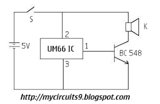
This doorbell circuit can be further enhanced by integrating features such as LED indicators to show when the doorbell is activated or by using a wireless system to eliminate the need for extensive wiring. The simplicity of this circuit allows for easy troubleshooting and modifications, making it a practical choice for basic doorbell applications.Here is the circuit diagram for simple door bell, you can assemble this circuit inside your room or home where as keep the switch outside your home or room that is easily noticable by the visitors. The working of this circuit is almost similar to my previous project. 🔗 External reference
Related Circuits
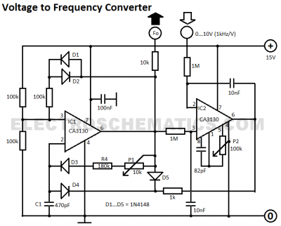
This voltage-to-frequency converter circuit features a voltage-controlled oscillator with a small deviation of 0.5%. The integrated circuit IC1 operates as a multivibrator. The voltage-to-frequency converter circuit is designed to convert an input voltage into a corresponding frequency output. The core...
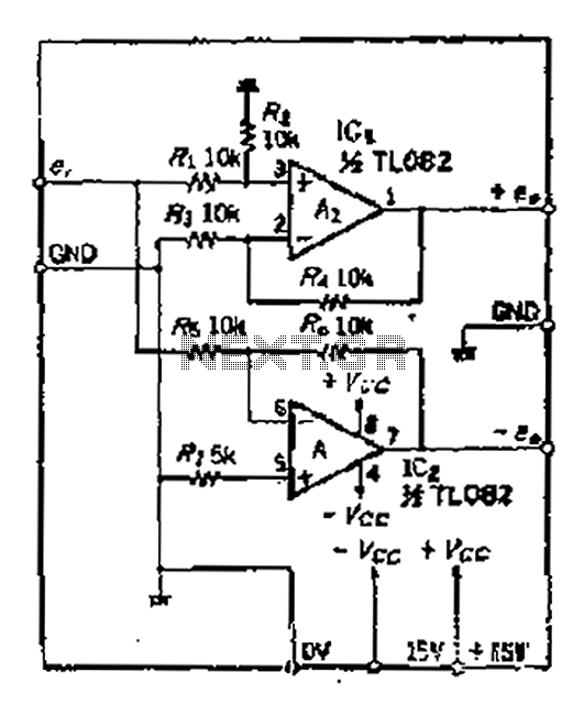
A balanced output is often associated with the positive phase amplifier output terminal of an operational amplifier, which is typically viewed as the inverting amplifier circuit. However, the reversed phase output can lead to a loss of balance in...
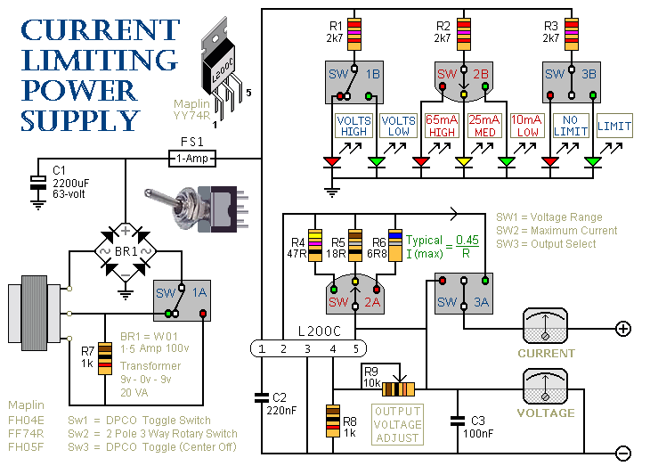
This is a 1-amp variable-voltage power supply unit (PSU) that adjusts the output voltage from approximately 3V to 24V. It features a current limiting option, which is particularly useful for initial power-ups or soak-testing equipment. SW3 acts as the...

The I2C PIC Interfacing Tutorial circuit is relatively straightforward; however, it requires careful verification to ensure that all connections are correct before initial operation. The primary components utilized in this circuit include the PIC18F452 microcontroller, the 24LC02B EEPROM, and...

An electronic calculator features an automatic counting interface circuit, as illustrated in the accompanying figures. Figure (a) depicts a stroke switch controlled via optocoupler B. Figure (b) shows the application of a reed switch (KR) for pulse control signals....
The following circuit illustrates a VHF pre-amplifier circuit diagram. This circuit utilizes the BFS17 transistor. Features: designed for VHF applications. The VHF pre-amplifier circuit is essential for enhancing weak radio frequency signals in the VHF (Very High Frequency) range, typically...
Warning: include(partials/cookie-banner.php): Failed to open stream: Permission denied in /var/www/html/nextgr/view-circuit.php on line 713
Warning: include(): Failed opening 'partials/cookie-banner.php' for inclusion (include_path='.:/usr/share/php') in /var/www/html/nextgr/view-circuit.php on line 713