
Alarm Circuit for Snoring Prevention by 555 Timer

The circuit operates on the principle of detecting snoring sounds through a microphone or sound sensor. When the sound level exceeds a predetermined threshold, the circuit activates a vibrator mechanism. This approach is particularly beneficial in situations where the use of audio alerts may disturb other individuals nearby.
The design typically includes a microphone, an amplifier to enhance the sound signal, and a comparator circuit to compare the amplified signal with a reference voltage representing the snoring threshold. If the snoring is detected, the comparator output triggers a relay or a transistor that controls the power to the vibrator.
Power supply considerations are crucial for this circuit, often utilizing a battery for portability and ease of use. The vibrator can be a small motor or a piezoelectric actuator, which provides sufficient tactile feedback to wake the user without generating noise.
Additional features may include adjustable sensitivity settings for the microphone, allowing customization based on the user's snoring patterns, and a timer to limit the duration of the alert. Incorporating an LED indicator can provide a visual cue when the circuit is active, ensuring the user is aware of its operation.
In summary, this circuit serves as an innovative solution for managing snoring in a discreet manner, enhancing sleep quality for both the individual and those nearby.The circuit was designed to produce a circuit that will alarm a sleeping person to prevent snoring by using a vibrator instead of an audio alert so as not.. 🔗 External reference
Related Circuits

This design presents an innovative approach to the Joule Thief (JT) circuit typically utilized in garden lights. Instead of directly charging a 1.2V battery from the solar cell and converting the power to operate a 3-volt LED, this circuit...
This is a simple proximity switch utilizing the IC 4049. The IC 4049 is a bipolar monolithic integrated circuit designed for metal detection systems and proximity sensing applications. It includes an oscillator formed by an external parallel resonant tank...

This is a lamp timer capable of operating two separate relay switches. Outputs can be in three (or restricted to two) states: OFF, delayed ON and constant ON. Delayed ON mode is indicated by the LEDs. The source code...

In this circuit, an LM339 quad voltage comparator is used to generate a time delay and control a high current output at low voltage. Approximately 5 amps of current can be obtained using a couple of fresh alkaline D...
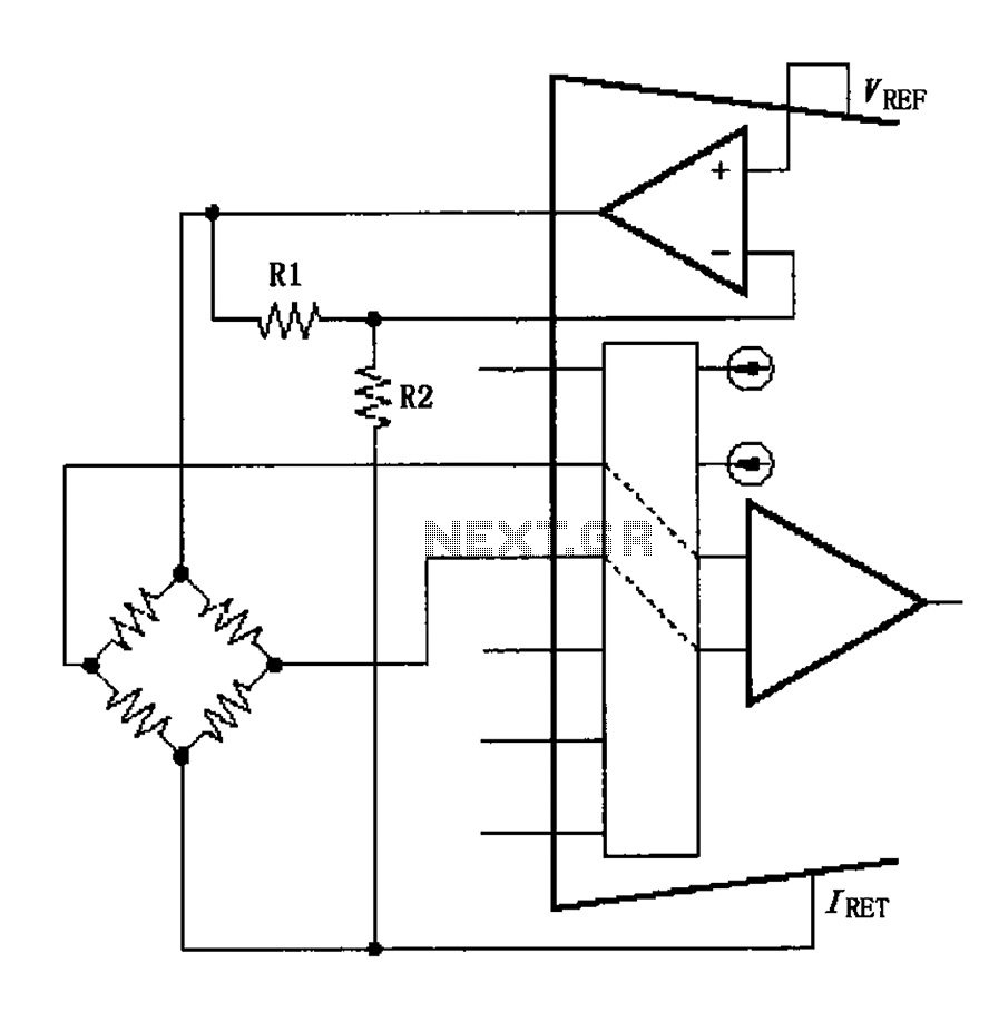
The circuit voltage source VREF excites the sensor bridge. The excitation voltage VEX is defined as VREF (1 + R1/R2), where the bridge is connected at both ends. The sensor bridge circuit is designed to convert a physical quantity, such...
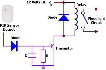
The circuit illustrates a 12V PIR sensor timer circuit diagram. Features include a 12 Volt DC supply, capable of activating a floodlight or other devices for a specified duration. The 12V PIR sensor timer circuit is designed to detect motion...