
12V PIR Sensor Timer
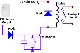
The 12V PIR sensor timer circuit is designed to detect motion and activate connected devices such as floodlights, security alarms, or other electronic equipment. The core component of this circuit is the Passive Infrared (PIR) sensor, which detects infrared radiation emitted by objects in its field of view, typically human bodies. When motion is detected, the sensor sends a signal to a timer circuit, which then controls the power supply to the connected load.
The circuit operates on a 12 Volt DC power supply, making it suitable for various applications in residential and commercial settings. The output of the PIR sensor is typically connected to a timer IC, such as the NE555 timer configured in a monostable mode. This configuration allows the timer to produce a single output pulse of a specified duration, which can be adjusted using external resistors and capacitors.
Upon activation, the timer output energizes a relay or a transistor switch that controls the floodlight or other connected devices. The relay provides isolation between the low voltage control circuit and the high voltage load, ensuring safety and reliability. The duration for which the floodlight remains on can be set according to the application requirements, allowing flexibility in operation.
Additional components may include diodes for flyback protection across the relay coil, capacitors for smoothing the power supply, and resistors for setting the sensitivity of the PIR sensor. Proper placement of the PIR sensor is crucial for optimal performance, as it should be positioned to cover the desired detection area without obstructions.
Overall, this circuit is an efficient solution for automatic lighting control, enhancing security and convenience in various environments.The following circuit shows about 12V PIR Sensor Timer Circuit Diagram. Features: 12 Volt DC, will turn on a floodlight or other device for a time .. 🔗 External reference
Related Circuits
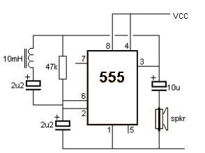
This metal detector electronic project schematic circuit is designed using a simple 555 timer integrated circuit. The schematic circuit requires a few external electronic components. The metal detector circuit utilizes the 555 timer IC in astable mode to generate a...

LCD initializations in 8051 C programming involve understanding the logic behind serial communication, including the duration of SIG pulse transmission and the necessary delays. These statements inform the compiler that a 16x2 LCD is connected to the defined pins...
This circuit turns off an amplifier or any other device when a low-level audio signal fed to its input is absent for at least 15 minutes. Pressing P1 switches the device on, supplying power to any appliance connected to...
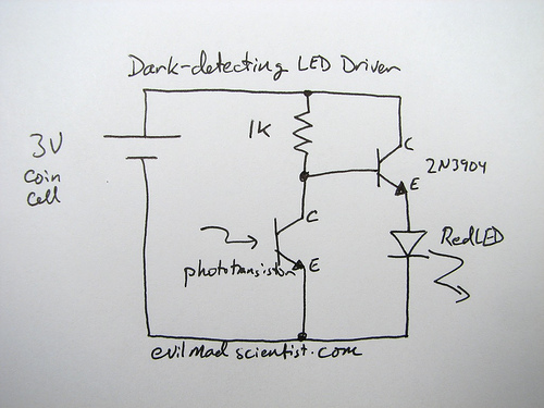
A circuit that uses a phototransistor to create a light-sensitive switch. When there is no light in the room, the LED connected to the phototransistor lights up, and when there is light, the LED turns off. Any schematic or...
The article presents a circuit concept that features an innovative method for detecting minimal shocks caused by potential earthquake tremors. This circuit is highly sensitive, capable of detecting tremors of magnitude 4 on the Richter scale, while remaining unaffected...
This device is designed for individuals seeking to achieve a tan while minimizing excessive exposure to sunlight. It utilizes electrolytic capacitors as one of its components. The tanning device operates by utilizing a controlled exposure mechanism that regulates the intensity...